Rogers PCBs are ideal for high-frequency and high-speed circuits because their advanced material composition provides an exceptionally stable dielectric constant (Dk), ultra-low dissipation factor (Df), and superior thermal management compared to standard FR-4 substrates. These properties are critical for maintaining signal integrity, minimizing signal loss, and ensuring reliable performance in demanding applications such as 5G communications, automotive radar, and aerospace systems where precision and consistency are non-negotiable.
Table of Contents
- What Exactly Are Rogers PCBs? A Look Beyond Standard FR-4
- The Core Electrical Properties That Define Rogers’ Superiority
- How Do Rogers PCBs Enhance Thermal Management and Reliability?
- A Practical Comparison: Rogers PCB vs. FR-4
- Which Rogers Material Series Is Right for Your Application?
- Where Are Rogers PCBs Making a Critical Impact? Real-World Applications
- Key Design and Fabrication Considerations for Rogers PCBs
- Conclusion: Why Investing in Rogers PCBs is a Future-Proof Decision
- Frequently Asked Questions (FAQ)
Why Rogers PCBs Are the Unrivaled Choice for High-Frequency and High-Speed Circuits
In the world of modern electronics, as data rates soar and frequencies climb into the gigahertz range, the very foundation of a circuit—the Printed Circuit Board (PCB)—comes under intense scrutiny. While standard FR-4 material has been the industry’s workhorse for decades, its limitations become glaringly apparent in high-performance applications. This is where Rogers’ high-frequency laminates enter the picture, not as a mere alternative, but as a critical enabling technology. Understanding why Rogers PCBs are the superior choice requires a deep dive into the material science that governs signal integrity and reliability at speed.
What Exactly Are Rogers PCBs? A Look Beyond Standard FR-4
At its core, a Rogers PCB is a circuit board fabricated using high-performance laminate materials developed by Rogers Corporation. Unlike FR-4, which is a composite of woven fiberglass cloth with an epoxy resin binder, Rogers materials often utilize a more sophisticated composition. This advanced engineering is precisely what equips them to handle the stringent demands of high-frequency and high-speed digital circuits, setting them apart in performance and application.
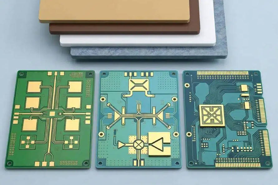
The Fundamental Difference: Ceramic-Filled PTFE vs. Epoxy-Glass
The primary distinction lies in the substrate’s composition. Many popular Rogers materials, such as those in the RT/duroid® series, use Polytetrafluoroethylene (PTFE), a synthetic fluoropolymer famous for its excellent dielectric properties. This base is often reinforced with ceramic fillers or woven glass to enhance mechanical stability and fine-tune its electrical characteristics. This ceramic-PTFE composite results in a material with significantly lower electrical losses and a more stable dielectric constant compared to the epoxy-glass structure of FR-4. This stability is the cornerstone of predictable circuit performance, especially as frequencies increase.
An Introduction to Rogers Corporation’s High-Performance Materials
Rogers Corporation is not just a single material but a broad portfolio of specialized laminates designed for specific performance tiers. Their product families, including the RO4000®, RT/duroid®, and RO3000® series, offer a spectrum of properties tailored to different applications, from commercial wireless infrastructure to mission-critical aerospace and defense systems. This variety allows engineers to select a material that precisely matches their electrical performance, thermal management, and cost requirements, a level of customization not available with generic FR-4.
The Core Electrical Properties That Define Rogers’ Superiority
To truly appreciate why engineers specify Rogers materials, we must examine the key electrical parameters that directly impact high-frequency signal behavior. It is in these metrics that the performance gap between Rogers and FR-4 becomes a chasm.
Stable Dielectric Constant (Dk): The Bedrock of Signal Integrity
The dielectric constant (Dk) of a PCB material determines the speed at which a signal propagates and influences the impedance of circuit traces. For high-frequency circuits, having a stable and consistent Dk is paramount. Rogers materials exhibit a Dk that remains remarkably stable across a wide range of frequencies and operating temperatures. In contrast, the Dk of FR-4 can fluctuate significantly as frequency increases, leading to unpredictable impedance, signal reflections, and a degradation of overall signal integrity. This stability makes Rogers PCBs ideal for designing controlled impedance transmission lines, filters, and couplers that perform as simulated.
Ultra-Low Dissipation Factor (Df): Minimizing Signal Loss at High Frequencies
The Dissipation Factor (Df), also known as loss tangent, quantifies how much of a signal’s energy is absorbed and lost as heat within the PCB substrate. At multi-gigahertz frequencies, this loss becomes a major factor. FR-4 has a relatively high Df (e.g., ~0.020), which can cause significant signal attenuation, especially over longer trace lengths. Rogers materials are engineered for an ultra-low Df (often as low as ~0.001-0.004), meaning a much larger portion of the signal’s power reaches its destination. This is crucial for applications like high-power amplifiers in 5G base stations or sensitive receivers in satellite systems, where every decibel of signal loss matters.
Exceptional Thermal Coefficient of Dk (TCDk): Ensuring Performance in Extreme Environments
The Thermal Coefficient of Dielectric Constant (TCDk) measures how much the Dk value changes with temperature. In applications like automotive radar or aerospace avionics, electronics must operate reliably across a vast temperature range. Rogers materials boast a very low TCDk, ensuring that circuit performance remains consistent whether the device is in a sub-zero environment or operating at high temperatures. This thermal stability prevents frequency shifting in sensitive components like filters and oscillators, a common problem in FR-4 based designs exposed to thermal cycling.
How Do Rogers PCBs Enhance Thermal Management and Reliability?
Beyond pure electrical performance, the physical and thermal properties of Rogers materials contribute significantly to the long-term reliability and robustness of the final product.
Superior Thermal Conductivity: Effectively Dissipating Heat
High-speed and high-power components generate significant heat. The ability of the PCB to conduct this heat away from the components is critical for preventing overheating and failure. Many Rogers laminates offer higher thermal conductivity than standard FR-4. This allows them to act as a more effective heat spreader, drawing thermal energy away from hotspots on active devices like power amplifiers and processors. This improved thermal management leads to lower operating temperatures, which directly translates to increased component lifespan and system reliability.
Low Z-Axis CTE: Guaranteeing Plated Through-Hole (PTH) Reliability
The Coefficient of Thermal Expansion (CTE) describes how much a material expands or contracts with temperature changes. A critical parameter is the Z-axis (thickness) CTE. Rogers materials typically have a Z-axis CTE that is much closer to that of copper. During thermal cycling (e.g., device power-up/down), this similarity in expansion rates puts significantly less stress on the plated through-holes (PTHs) and vias that connect different layers of the PCB. In contrast, the higher Z-axis CTE of FR-4 can lead to barrel cracking and via failures over time, a major reliability concern in mission-critical systems.

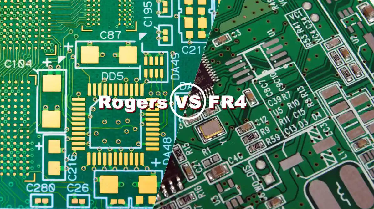
A Practical Comparison: Rogers PCB vs. FR-4
To summarize the key differences, the following table provides a head-to-head comparison of typical properties for a high-performance Rogers material versus standard FR-4.
| Property | High-Performance Rogers (e.g., RO4350B) | Standard FR-4 | Impact on High-Frequency/Speed Circuits |
|---|---|---|---|
| Dielectric Constant (Dk) @ 10 GHz | ~3.48 (Very Stable) | ~4.5 (Varies with frequency) | Stable Dk ensures predictable impedance and signal timing. |
| Dissipation Factor (Df) @ 10 GHz | ~0.0037 (Ultra-Low Loss) | ~0.020 (High Loss) | Low Df minimizes signal attenuation, preserving signal strength. |
| Thermal Coefficient of Dk (TCDk) | ~50 ppm/°C (Excellent Stability) | ~200-300 ppm/°C (Poor Stability) | Ensures consistent performance across operating temperatures. |
| Thermal Conductivity | ~0.69 W/mK (Good) | ~0.25 W/mK (Poor) | Better heat dissipation improves reliability and component life. |
| Moisture Absorption | ~0.06% (Very Low) | ~0.25% (Moderate) | Low absorption prevents changes in Dk/Df in humid environments. |
| Cost | Higher | Lower | Performance justifies the cost in demanding applications. |
Which Rogers Material Series Is Right for Your Application?
Choosing the correct Rogers material is a critical design step. The portfolio is intentionally diverse to meet various performance and cost targets.
The RO4000® Series: The Industry Standard for Performance and Processability
Materials like RO4350B™ and RO4003C™ are perhaps the most popular high-frequency laminates in the industry. They are glass-reinforced hydrocarbon/ceramic thermoset materials, which means they can be processed using standard FR-4 fabrication techniques. This makes them a cost-effective choice for upgrading from FR-4 without requiring a complete overhaul of the manufacturing process. They offer excellent high-frequency performance and are widely used in cellular base station antennas, power amplifiers, and automotive radar.
The RT/duroid® Series: Ultimate Performance for Demanding Applications
The RT/duroid series, such as RT/duroid 5880, represents the pinnacle of performance. These are PTFE composites reinforced with glass microfibers, resulting in extremely low Dk and Df values that are stable over a vast frequency range. Their exceptional properties make them the go-to choice for the most demanding microwave and millimeter-wave applications, including satellite communications, aerospace and defense electronics, and high-frequency test and measurement equipment where signal purity is absolute.
The RO3000® Series: Cost-Effective Solutions for Commercial RF
The RO3000® series of laminates are ceramic-filled PTFE composites intended for use in commercial, cost-sensitive RF applications. Materials like RO3003™ offer excellent Dk stability over temperature and frequency. They are commonly found in automotive cruise control systems, wireless communication infrastructure, and remote meter readers where consistent performance is required at a competitive price point.
Where Are Rogers PCBs Making a Critical Impact? Real-World Applications
The theoretical benefits of Rogers materials translate into tangible advantages across numerous cutting-edge industries:
- Powering the 5G and 6G Revolution: The high frequencies and complex modulation schemes of 5G/6G demand low-loss materials for antennas, power amplifiers, and filters to maximize signal range and data throughput.
- Enhancing Automotive Safety: Advanced Driver-Assistance Systems (ADAS) and autonomous vehicles rely on 77 GHz radar sensors. Rogers PCBs ensure these sensors operate with extreme accuracy and reliability, regardless of weather conditions.
- Advancing Aerospace & Defense: From satellite communication payloads to phased-array radar systems, the reliability and stable performance of Rogers materials in extreme environments are indispensable.
- High-Speed Digital: In enterprise-level servers, routers, and data centers, Rogers materials are used to minimize loss and signal distortion in backplanes and interconnects handling data rates of 56 Gbps and beyond.
Key Design and Fabrication Considerations for Rogers PCBs
While materials like the RO4000 series are processed similarly to FR-4, some PTFE-based materials require specialized handling. Engineers must consider factors like drilling parameters, surface preparation for plating, and thermal profiles for lamination. Partnering with a PCB fabricator experienced with Rogers materials is crucial to ensure a successful manufacturing run. Although the raw material cost is higher than FR-4, this investment is often justified by superior performance, higher manufacturing yields for complex designs, and the prevention of costly field failures, making the total cost of ownership lower in the long run.
Conclusion: Why Investing in Rogers PCBs is a Future-Proof Decision
In conclusion, the decision to use Rogers PCBs over standard FR-4 is driven by the uncompromising demands of high-frequency and high-speed electronics. Their superiority is not a matter of opinion but a quantifiable reality rooted in material science. By providing a stable dielectric constant, ultra-low signal loss, robust thermal management, and exceptional reliability, Rogers materials empower engineers to push the boundaries of technology. For any design where signal integrity is paramount and performance cannot be compromised, Rogers PCBs are not just the ideal choice—they are the essential foundation for innovation and success.
Frequently Asked Questions (FAQ)
Can you mix Rogers and FR-4 materials in a hybrid PCB stack-up?
Yes, this is a very common and cost-effective practice. A hybrid or mixed dielectric stack-up involves using Rogers material for the critical high-frequency signal layers (e.g., the outer layers for RF traces) and standard FR-4 for the inner power and ground plane layers. This approach delivers the necessary RF performance where it’s needed while leveraging the lower cost of FR-4 for less critical parts of the design, providing a balanced solution for cost and performance.
What is the main disadvantage of using Rogers PCB?
The primary disadvantage of Rogers PCBs is their higher material cost compared to FR-4. A sheet of Rogers laminate can be several times more expensive than its FR-4 counterpart. Additionally, some pure PTFE-based Rogers materials can require specialized fabrication processes, which may add to the manufacturing cost and limit the choice of fabricators. However, this cost is often justified by the significant performance gains and increased reliability.
How does moisture absorption affect high-frequency performance?
Moisture absorption can significantly degrade high-frequency performance. Water has a high dielectric constant (Dk) of around 70. When a PCB substrate absorbs moisture from the environment, it effectively changes the overall Dk and increases the dissipation factor (Df) of the material. This can lead to impedance mismatches, increased signal loss, and unpredictable circuit behavior. Rogers materials have very low moisture absorption rates, ensuring their electrical properties remain stable and reliable even in humid conditions.
Rogers PCB, high-frequency circuits, high-speed PCB, Rogers material, Why use Rogers PCB, Rogers vs FR-4, RF PCB material, stable dielectric constant, low dissipation factor, Rogers RO4350B, thermal management in high-speed circuits, 5G PCB material