The primary difference between a Rigid-Flex PCB and a Flex PCB lies in their construction and intended application. A Flex PCB is a circuit board built entirely on a flexible substrate, designed to bend and fold, while a Rigid-Flex PCB is a hybrid board that integrates rigid circuit sections with flexible circuits into a single, unified piece. This integration eliminates the need for connectors between rigid boards, dramatically increasing reliability and enabling complex, three-dimensional designs. While Flex PCBs offer unparalleled flexibility and space-saving, Rigid-Flex PCBs provide a robust, highly reliable solution for mission-critical applications where structural support and dense component mounting are essential.
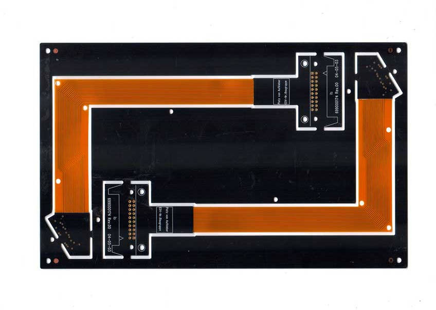
Table of Contents
- What is a Flex PCB (Flexible Printed Circuit)?
- What is a Rigid-Flex PCB?
- Key Differences: Rigid-Flex vs. Flex PCB Head-to-Head
- The Cost Equation: Why is Rigid-Flex Significantly More Expensive?
- Application and Use Cases: Where Does Each Technology Shine?
- Making the Right Choice: Which PCB is Right for Your Project?
- Conclusion: Beyond Flexibility – A Strategic Engineering Decision
What is a Flex PCB (Flexible Printed Circuit)?
A Flex PCB, or flexible printed circuit, is an electronic circuit built on a pliant, adaptable substrate instead of a traditional rigid board like FR-4. Think of it as an electronic ribbon that can be bent, twisted, and folded to fit into compact or unconventionally shaped electronic devices. Their primary advantage is the ability to conform to three-dimensional spaces, reducing the overall size and weight of the final product. These circuits are designed for both static applications, where they are bent once during assembly, and dynamic applications, where they must endure repeated flexing throughout the product’s lifespan, such as in a laptop hinge or a printer carriage.
Core Composition and Materials
The foundation of a flex circuit’s adaptability lies in its materials. The most common base substrate is polyimide (PI), a high-performance polymer known for its excellent thermal stability, chemical resistance, and robust mechanical properties. Thin layers of conductive material, typically rolled-annealed (RA) copper, are bonded to the polyimide base. This type of copper is chosen for its superior flexibility and resistance to the stress of repeated bending compared to standard electro-deposited (ED) copper used in rigid boards. A coverlay, which is essentially a laminated layer of polyimide with an adhesive, is applied over the copper traces to insulate and protect the circuitry from environmental factors like moisture and dust.
The Role of Stiffeners in Flex PCBs
While the core purpose of a flex circuit is flexibility, certain areas often require reinforcement. This is where stiffeners come in. A stiffener is a piece of rigid material, such as FR-4 or polyimide, that is laminated to a specific area of the flex circuit. They are not electrically connected to the circuit. Their purpose is purely mechanical: to provide support for mounting components and connectors, to meet specific thickness requirements for ZIF (Zero Insertion Force) connectors, or to control the bending in designated areas. The strategic use of stiffeners can provide a cost-effective alternative to a full rigid-flex board when only localized rigidity is needed.
What is a Rigid-Flex PCB?
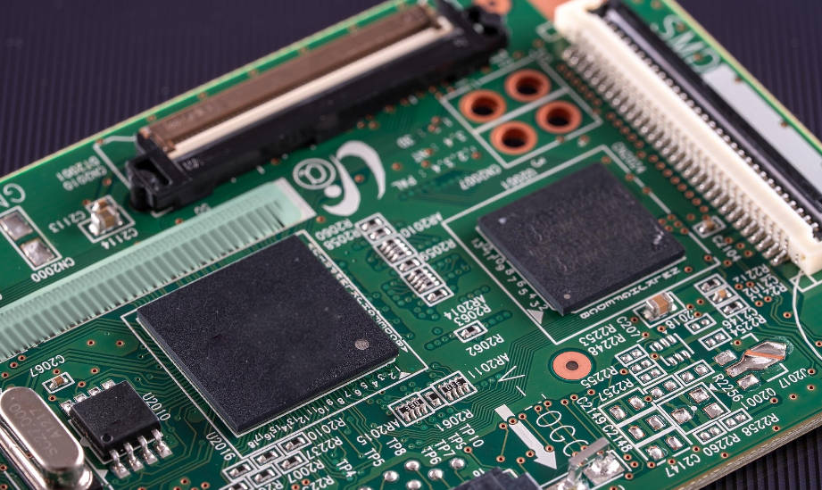
A Rigid-Flex PCB is an advanced hybrid circuit board that combines the best attributes of both rigid and flexible circuits into a single, seamlessly integrated component. It consists of one or more rigid circuit boards interconnected by flexible circuit sections. Unlike a flex circuit with stiffeners, the rigid sections of a rigid-flex board are fully functional, multi-layered circuits capable of supporting dense component populations, including BGA packages and other high-pin-count devices. This integrated structure eliminates the need for cables, wires, and connectors that would traditionally link separate rigid boards, thereby forming a more reliable and streamlined electromechanical solution.
A Hybrid Engineering Marvel: Construction and Layers
The construction of a rigid-flex PCB is a sophisticated process. It starts with fabricating the flexible circuit layers, which are then sandwiched between the rigid layers (typically made of FR-4). The layers are laminated together in a high-temperature, high-pressure process using a specialized no-flow prepreg bonding film. This ensures a durable and permanent bond between the dissimilar materials. Plated through-holes (PTH) extend through both the rigid and flex layers, creating robust electrical connections throughout the entire board. The result is a single, cohesive unit that can be bent and folded at the flexible sections while providing stable, rigid platforms for sensitive components.
How are Rigid-Flex Boards Manufactured?
Manufacturing rigid-flex PCBs is significantly more complex than producing either rigid or flex boards alone. The process requires precise alignment of multiple layers of different materials, each with its own thermal and mechanical properties. Specialized equipment and expertise are necessary to manage the lamination process and ensure there are no air gaps or delamination between the rigid and flexible sections. The drilling and plating processes are also more challenging, as they must create reliable connections through both FR-4 and polyimide. This inherent complexity leads to longer lead times, lower manufacturing yields, and, consequently, a higher unit cost compared to other PCB technologies.
Key Differences: Rigid-Flex vs. Flex PCB Head-to-Head
Understanding the fundamental distinctions between these two technologies is crucial for making the right design choice. While both offer solutions for compact electronics, their structural differences lead to vastly different performance characteristics, costs, and ideal use cases. The primary differentiator is the level of integration and structural support offered.
| Feature | Flex PCB | Rigid-Flex PCB |
|---|---|---|
| Structure | A single, continuous flexible substrate (e.g., polyimide). Rigidity is added locally with non-conductive stiffeners. | A hybrid construction integrating rigid board sections (e.g., FR-4) and flexible sections into a single, multi-layered circuit. |
| Component Support | Limited to lightweight, SMT components. Stiffeners are required to support heavier components and connectors. | Excellent support for dense, high-pin-count components (e.g., BGAs, QFPs) on the rigid sections. |
| Interconnect Reliability | Reliable, but often relies on external connectors (e.g., ZIF) to connect to other boards, which can be points of failure. | Extremely high reliability due to the elimination of connectors and solder joints between boards. Connections are made internally via plated through-holes. |
| Flexibility | Highly flexible throughout the entire board, ideal for dynamic flexing and conforming to tight, complex shapes. | Flexibility is confined to the specific flexible “hinge” sections. The rigid parts provide structural integrity. |
| Cost | More expensive than standard rigid PCBs but significantly less expensive than rigid-flex. | The most expensive option due to complex materials, difficult fabrication processes, and lower manufacturing yields. |
| 3D Design Capability | Excellent for folding into 3D shapes, but lacks self-supporting structure. | Superior for creating self-supporting, complex 3D electromechanical assemblies that maintain their shape. |
The Cost Equation: Why is Rigid-Flex Significantly More Expensive?
One of the most critical factors in the decision-making process is cost. It is no secret that rigid-flex PCBs carry a premium price tag. This higher cost is not arbitrary; it is a direct result of the complex materials, intricate manufacturing processes, and the higher level of engineering precision required to produce a reliable final product. Understanding these cost drivers is essential for justifying the investment in this advanced technology.
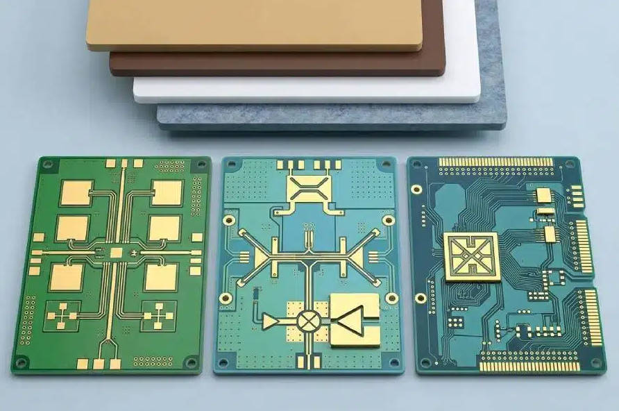
Material Complexity and Sourcing
Rigid-flex boards require a wider and more specialized set of materials than their counterparts. This includes not only the standard FR-4 and polyimide but also specialized bonding adhesives like no-flow prepreg. These materials must be carefully selected for compatibility to ensure they can withstand the stresses of lamination and thermal cycling without delaminating or failing. Sourcing these specialized materials often involves fewer suppliers and higher costs, which directly contributes to the overall price of the board.
Complex Fabrication Processes and Lower Yields
The manufacturing journey of a rigid-flex board is far more convoluted than that of a standard PCB. It involves a combination of both rigid and flex PCB fabrication steps, executed in a precise sequence. Processes like plasma etching to prepare the polyimide surface, multi-stage lamination cycles, and laser drilling must be perfectly controlled. This complexity inevitably leads to a higher probability of manufacturing defects, resulting in lower production yields. To compensate for the boards that fail quality control, manufacturers must factor this attrition rate into the price of the successful units.
Total Cost of Ownership (TCO): The Hidden Savings
While the upfront unit cost of a rigid-flex PCB is high, it can sometimes lead to a lower Total Cost of Ownership (TCO). This is achieved by eliminating the need for multiple PCBs, connectors, cables, and the associated manual labor for assembly and testing. By integrating these elements into a single piece, you reduce the bill of materials (BOM), simplify the supply chain, shorten assembly time, and remove potential points of failure. For complex, mission-critical devices, the enhanced reliability and reduced assembly costs can outweigh the initial board price, making rigid-flex the more economical choice in the long run.
Application and Use Cases: Where Does Each Technology Shine?
The choice between flex and rigid-flex technology is ultimately dictated by the specific requirements of the application. Each has a distinct set of strengths that make it the ideal solution for different engineering challenges, from consumer electronics to aerospace and defense systems.
Common Use Cases for Flex PCBs
Flex PCBs are the go-to solution when space, weight, and the need for dynamic or static bending are the primary design drivers. Their ability to replace bulky wire harnesses makes them invaluable in compact devices.
- Consumer Electronics: Found in digital cameras, smartphones, and laptops, connecting displays, keyboards, and sensors where space is at a premium and repeated flexing may occur.
- Automotive: Used in dashboard clusters, infotainment systems, and lighting controls where circuits must fit into contoured spaces.
- Printers and Scanners: The moving print head or scanning bar is almost always connected via a dynamic flex circuit designed to withstand millions of flex cycles.
- Wearable Technology: Smartwatches, fitness trackers, and smart clothing rely on flex circuits to conform to the human body and move with the user.
When to Choose Rigid-Flex PCBs
Rigid-flex is reserved for high-performance, high-reliability applications where the cost is justified by the need for superior durability, streamlined 3D design, and the elimination of failure-prone connectors.
- Aerospace and Defense: Used in avionics, missile guidance systems, and satellite equipment where absolute reliability is non-negotiable and resistance to shock and vibration is paramount.
- Medical Devices: Critical in devices like pacemakers, defibrillators, and high-end imaging equipment (CT, MRI), where compact size and unwavering performance can be life-saving.
- Advanced Robotics and Drones: The integrated structure provides a durable and lightweight solution for connecting sensors, motors, and processors in a compact, moving frame.
- High-End Test Equipment: Provides a stable platform for sensitive measurement components while allowing the overall device to be more compact and portable.
Making the Right Choice: Which PCB is Right for Your Project?
Selecting the appropriate PCB technology is a critical engineering decision that impacts performance, reliability, and budget. It requires a thorough analysis of your project’s mechanical, electrical, and financial constraints. Answering a few key questions can help guide your team toward the optimal solution.
Key Questions to Ask Your Engineering Team
- What is the primary mechanical requirement? If the goal is simply to connect two boards in a tight space with a one-time bend, a simple flex circuit is likely sufficient. If you need a self-supporting 3D structure with high shock resistance, rigid-flex is the better choice.
- What types of components will be mounted? If you are using only lightweight SMT components, a flex board with stiffeners may work. If your design includes dense, heavy, or high-pin-count components like BGAs, you need the stable platform of a rigid-flex board.
- How critical is interconnect reliability? For a consumer product, a ZIF connector might be an acceptable risk. For a medical or aerospace device where failure could have catastrophic consequences, the connector-free architecture of a rigid-flex board is essential.
- What is the true project budget? Consider both the upfront board cost and the Total Cost of Ownership. Will the reduced assembly time and higher reliability of a rigid-flex design save money over the product’s lifecycle?
A Quick Decision-Making Checklist
- Choose Flex PCB if:
- Your primary need is to save weight and space.
- The circuit requires dynamic flexing (repeated bending).
- Cost is a major constraint.
- Component density is low, and connectors are simple.
- The design involves connecting two static boards in a non-linear way.
- Choose Rigid-Flex PCB if:
- Absolute reliability is the top priority.
- The design must withstand high shock and vibration.
- You need to mount dense or heavy components on a stable surface.
- You are creating a complex, three-dimensional assembly.
- The long-term TCO justifies a higher initial investment.
Conclusion: Beyond Flexibility – A Strategic Engineering Decision
In the end, the debate between Rigid-Flex PCB and Flex PCB is not merely about which one bends better. It’s a strategic decision rooted in the core requirements of your product. Flex PCBs are the masters of adaptation and cost-efficiency, providing an elegant solution for connecting components in compact, lightweight devices. They excel where point-to-point connection in a constrained space is the main challenge. Rigid-Flex PCBs, on the other hand, are the champions of integration and unwavering reliability. They represent a holistic system solution, creating robust, self-contained electronic modules for the most demanding environments. By carefully evaluating your application’s needs for reliability, component support, mechanical stress, and overall budget, you can confidently select the technology that will not only fit your design but also ensure its long-term success.