A rigid-flex PCB is a hybrid circuit board that combines elements from both hardboard and flexible circuits, creating a single, integrated solution. These advanced boards are designed with rigid sections, typically made from FR-4, which house components and connectors, seamlessly connected by flexible, bendable sections made from materials like polyimide. This unique construction eliminates the need for traditional connectors, cables, and wires between rigid boards, resulting in a more reliable, compact, and lightweight electronic assembly. By allowing for three-dimensional design configurations, rigid-flex PCBs offer unparalleled solutions for complex and space-constrained electronic devices.
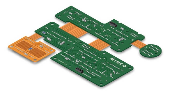
Table of Contents
- What Is a Rigid-Flex PCB?
- Deconstructing the Rigid-Flex PCB Structure
- Why Choose Rigid-Flex PCBs? Unpacking the Key Benefits
- Rigid-Flex vs. Alternatives: A Comparative Analysis
- Where are Rigid-Flex Circuits Used? Typical Applications
- Crucial Design and Manufacturing Considerations
- Conclusion: The Future of Interconnect Technology
- Frequently Asked Questions (FAQ)
What Is a Rigid-Flex PCB?
A Rigid-Flex PCB, or rigid-flex printed circuit board, is a sophisticated type of circuit board that features a combination of both rigid and flexible circuit substrates laminated together into a single, unified structure. The rigid areas serve as stable platforms for mounting SMT (Surface-Mount Technology) and through-hole components, providing the mechanical support and density of a traditional hardboard. The flexible areas, on the other hand, provide dynamic, pliable interconnections between the rigid sections, allowing the board to be bent, twisted, and folded to fit into confined or unconventionally shaped enclosures.
This hybrid approach effectively eliminates the most common failure points in electronic assemblies: connectors and hand-soldered wires. By integrating the connections directly into the board’s structure, rigid-flex technology offers a significant leap in reliability, especially in applications subject to high vibration or shock. The ability to design in three dimensions also unlocks new possibilities for product miniaturization and complex form factors that would be impossible to achieve with standard rigid boards and cables.
Deconstructing the Rigid-Flex PCB Structure
Understanding the anatomy of a rigid-flex PCB is key to appreciating its capabilities. The structure is a carefully engineered stack-up of different materials, each serving a specific purpose. It can be broken down into three primary areas: the rigid sections, the flexible sections, and the crucial transition zones where they meet.
The Rigid Sections: The Foundation
The rigid portions of a rigid-flex circuit are constructed similarly to a standard PCB. They are typically made from FR-4 (Flame Retardant 4), a glass-reinforced epoxy laminate material known for its rigidity, electrical insulation properties, and affordability. These sections can have multiple layers of copper traces and planes, providing the necessary density for complex component mounting. They are the “workhorse” areas of the board, supporting heavy components, connectors, and processors while providing the structural integrity needed for the final assembly.
The Flexible Sections: The Interconnect Bridge
The flexible parts are what give rigid-flex PCBs their name and unique functionality. These sections are built using a pliable substrate, most commonly Polyimide (PI), a polymer celebrated for its excellent thermal stability, chemical resistance, and mechanical robustness. A thin layer of copper is bonded to the polyimide to form the conductive traces. An adhesive layer is often used to bond the copper to the polyimide, although adhesive-less constructions are preferred for applications requiring higher flexibility and reliability. The entire flexible section is then protected by a thin, flexible soldermask called a coverlay, which insulates the traces while allowing the section to bend freely.
The Critical Transition Zone
The area where the rigid material gives way to the flexible material is known as the transition zone. This is the most complex and critical part of a rigid-flex design. Proper engineering in this zone is essential to prevent mechanical stress and ensure long-term reliability. Designers must carefully manage the transition of traces from the rigid to the flex area, often using filleting (adding extra copper at the trace/pad interface) and ensuring a smooth, gradual change in width. Vias (plated through-holes) should be kept away from the immediate bend area to avoid creating stress points that could lead to fractures over time.
Why Choose Rigid-Flex PCBs? Unpacking the Key Benefits
The adoption of rigid-flex circuits is driven by a powerful set of advantages that solve many modern electronic design challenges. While the initial board cost can be higher than traditional solutions, the total cost of ownership is often lower due to simplified assembly and enhanced product reliability.
Enhanced Reliability and Durability
By eliminating connectors, ribbon cables, and hand-soldered wire harnesses, rigid-flex PCBs drastically reduce the number of potential failure points. Solder joints and connector interfaces are notoriously susceptible to failure from vibration, shock, and thermal cycling. A rigid-flex design integrates these connections into a single, robust part, creating an inherently more reliable product. This is why they are a top choice for mission-critical applications in the aerospace, military, and medical industries where failure is not an option.
Superior Space and Weight Savings
Perhaps the most significant benefit is the ability to achieve 3D packaging and miniaturization. Rigid-flex circuits can be folded and bent to fit into the tightest of spaces and complex geometries. This eliminates the space consumed by bulky cables and connectors, leading to smaller, lighter, and more ergonomic end products. A single rigid-flex board can replace multiple rigid PCBs, their connectors, and the interconnecting cables, resulting in weight reductions of up to 75%.
Streamlined Assembly and Reduced Overall Costs
While the bare board cost of a rigid-flex PCB is higher, it often leads to a lower total cost of ownership. Assembly is simplified because instead of manually connecting multiple boards with wires and cables, a single rigid-flex board is installed. This reduces manual labor, minimizes the risk of human error during assembly (like miswiring), and lowers the bill of materials (BOM) by removing the need for separate cables and connectors. Faster, more repeatable assembly processes translate directly into cost savings on the production line.
Improved Electrical Performance and Signal Integrity
The uniform, etched traces within the flexible sections offer controlled impedance and more predictable electrical characteristics compared to manually routed wires. This leads to better signal integrity, reduced noise, and improved performance, especially in high-frequency applications. The direct, connector-less pathways minimize signal loss and distortion, ensuring that sensitive data is transmitted reliably between different parts of the circuit.
Rigid-Flex vs. Alternatives: A Comparative Analysis
To fully appreciate the value of rigid-flex technology, it’s helpful to compare it against traditional interconnection methods, such as a set of rigid boards connected with wires/cables, and purely flexible circuits.
| Feature | Rigid-Flex PCB | Rigid PCB + Wires/Connectors | Flexible PCB |
|---|---|---|---|
| Reliability | Very High (Fewer solder joints, integrated connections) | Low (Many failure points at connectors and solder joints) | High (No connectors, but lacks component support) |
| Space Efficiency | Excellent (Enables 3D designs, highly compact) | Poor (Connectors and cables are bulky) | Excellent (Highly flexible, but needs stiffeners for components) |
| Assembly Time | Fast (Single component installation) | Slow (Requires manual connection of multiple parts) | Moderate (Requires careful handling and mounting) |
| Vibration Resistance | Excellent (Low mass and integrated structure) | Poor (Connectors can loosen or fail) | Good (Flexible nature absorbs some vibration) |
| Initial Cost | High | Low | Moderate |
| Component Support | Excellent (Rigid sections provide robust mounting) | Excellent (Standard rigid board mounting) | Poor (Requires added stiffeners for most components) |
Where are Rigid-Flex Circuits Used? Typical Applications
The unique advantages of rigid-flex PCBs make them the ideal choice for a wide range of demanding industries and products where space, weight, and reliability are paramount.
Aerospace and Defense
In avionics, satellites, and military equipment, electronics must withstand extreme temperatures, shock, and vibration. The high reliability and significant weight savings of rigid-flex circuits are critical. They are used in guidance systems, cockpit instrumentation, and communication arrays where failure could have catastrophic consequences.
Medical Devices
The medical field relies on miniaturization and absolute reliability. Rigid-flex PCBs are found in devices like pacemakers, defibrillators, digital imaging probes, and surgical tools. Their ability to fit into small, organically shaped devices while ensuring flawless performance is essential for patient health and safety.
Consumer Electronics
Modern gadgets like smartphones, laptops, digital cameras, and VR headsets constantly push the boundaries of size and performance. Rigid-flex PCBs are the enabling technology behind these sleek designs, connecting mainboards to displays, cameras, and sensors within tightly packed enclosures.
Automotive Systems
Cars are becoming increasingly sophisticated, with complex electronics for engine control units (ECUs), GPS, infotainment systems, and advanced driver-assistance systems (ADAS). Rigid-flex boards help manage the intricate wiring in confined spaces like the dashboard and engine bay, while also providing the durability needed to survive the harsh automotive environment.
Crucial Design and Manufacturing Considerations
Designing a rigid-flex PCB is more complex than designing a standard rigid board. Success requires careful attention to the unique mechanical and electrical challenges posed by the hybrid structure.
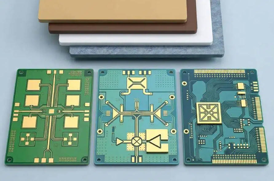
Material Selection
Choosing the right materials is foundational. The choice of polyimide for the flex section, the type of adhesive (or choosing an adhesive-less build), and the FR-4 for the rigid sections all impact the board’s performance, flexibility, and cost. High-frequency applications may require specialized materials with low dielectric loss.
Bend Radius and Flexibility
One of the most critical design rules is defining the minimum bend radius. Forcing a flex circuit to bend too tightly will stress the copper traces and can lead to fractures. A general rule of thumb is that the minimum bend radius should be at least 10 times the thickness of the flexible section for dynamic applications (where it bends repeatedly) and 6 times for static “bend-to-install” applications.
Layer Stack-up and Transition Design
The layer stack-up must be planned meticulously. This includes ensuring symmetrical construction to prevent warping and carefully planning how traces will route across the transition zone. Traces should cross the bend area perpendicular to the bend line to minimize stress. Furthermore, using staggered vias and smooth, curved traces instead of sharp 90-degree angles can significantly improve the board’s durability.
Conclusion: The Future of Interconnect Technology
Rigid-flex PCBs represent a powerful evolution in electronic interconnect technology. By merging the stability of rigid boards with the versatility of flexible circuits, they offer an elegant solution to the persistent challenges of space, weight, and reliability. While they demand more complex design and manufacturing processes, the benefits—from streamlined assembly and reduced costs to superior durability and performance—are undeniable. As electronic devices continue to become smaller, smarter, and more integrated, the demand for innovative, three-dimensional solutions like rigid-flex PCBs will only continue to grow, solidifying their place as a cornerstone of modern electronics design.
Frequently Asked Questions (FAQ)
1. How much do rigid-flex PCBs cost?
Rigid-flex PCBs have a higher initial unit cost than traditional rigid boards due to more complex materials and manufacturing processes. However, they often result in a lower total assembled cost by eliminating connectors and cables, reducing assembly labor, and increasing product reliability, which minimizes warranty and repair costs.
2. What is the difference between flex and rigid-flex PCBs?
A purely flexible PCB is made entirely of flexible materials like polyimide. It is excellent for dynamic flexing and simple interconnections but lacks the mechanical support to mount heavy or dense components without added stiffeners. A rigid-flex PCB integrates rigid sections (like FR-4) that provide robust platforms for component mounting, combining the best of both worlds.
3. What materials are used in rigid-flex circuits?
The most common materials are FR-4 for the rigid sections and Polyimide (PI) for the flexible sections. Other materials include copper foils for traces, adhesives for bonding layers, and coverlays (a flexible soldermask) to protect the flexible circuitry.