Is an aluminum PCB suitable for high-frequency circuits? The short answer is that standard aluminum printed circuit boards (PCBs) are generally not suitable for high-frequency circuits due to the high signal loss and unstable dielectric constant of their traditional epoxy isolation layers. However, when an aluminum base is combined with specialized high-frequency laminates—such as PTFE or Rogers materials in a hybrid PCB stack-up—aluminum becomes an exceptional choice. This hybrid approach perfectly balances the stringent signal integrity requirements of radio frequency (RF) and microwave applications with the superior thermal management capabilities inherent to aluminum metal core PCBs (MCPCBs).
As electronic devices continue to shrink while their processing power and operating frequencies increase, engineers face a dual challenge: maintaining signal integrity at high gigahertz (GHz) ranges and managing the massive amounts of heat generated by high-power components. High-frequency circuits, such as those used in 5G telecommunications, automotive radar, and aerospace communications, require precise impedance control. Traditional FR4 materials often fall short in these applications, prompting designers to explore alternative substrates, including metal-backed boards.
This comprehensive guide delves into the intersection of metal core technology and high-frequency circuit design. We will explore the physical properties of aluminum PCBs, analyze their limitations in RF applications, and uncover the advanced manufacturing techniques that allow engineers to leverage the thermal benefits of aluminum without compromising high-frequency signal integrity.
Why Traditional Aluminum PCBs Struggle with High Frequencies
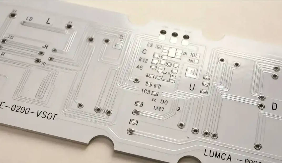
To understand why standard aluminum PCBs are typically rejected for high-frequency applications, one must examine their fundamental construction. A standard aluminum PCB consists of three primary layers: the copper circuit layer, a dielectric isolation layer, and the aluminum base plate. The critical component dictating high-frequency performance is not the aluminum itself, but rather the dielectric isolation layer sandwiched between the copper and the metal core.
In standard aluminum PCBs, primarily designed for the LED lighting industry and power converters, the dielectric layer is typically composed of an epoxy-based resin filled with thermally conductive ceramic particles (like alumina or boron nitride). While this formulation is fantastic for transferring heat away from hot components, its electrical properties are highly detrimental to fast-switching, high-frequency signals. Standard thermal dielectrics prioritize thermal conductivity over electrical signal preservation, leading to a host of signal integrity issues when operating in the megahertz (MHz) or gigahertz (GHz) ranges.
The Role of Dielectric Constant (Dk) and Signal Loss
The dielectric constant (Dk), also known as relative permittivity, measures a material’s ability to store electrical energy in an electric field. For high-frequency circuits, a low and highly stable Dk is absolutely critical. Standard aluminum PCB dielectrics typically exhibit a Dk ranging from 4.5 to 7.0, which is significantly higher than specialized RF materials (which hover around 2.2 to 3.5). Furthermore, this Dk value fluctuates wildly with changes in temperature and frequency, making it impossible to maintain consistent impedance along transmission lines.
Equally problematic is the Dissipation Factor (Df), or loss tangent. High-frequency signals are incredibly sensitive to attenuation. The standard thermally conductive epoxy used in basic aluminum PCBs has a relatively high Df (often above 0.015). As frequency increases, the signal energy absorbed and dissipated as heat by the dielectric material scales up exponentially. In an RF or microwave circuit, this translates to severe signal degradation, reduced transmission range, and poor signal-to-noise ratios. Therefore, relying on standard aluminum PCB dielectrics for anything above a few hundred megahertz is a recipe for system failure.
Parasitic Capacitance and Impedance Control Challenges
Another profound challenge stems from the physical geometry of an aluminum PCB. To maximize heat transfer, the dielectric isolation layer is manufactured to be extremely thin—typically between 50 to 150 micrometers (2 to 6 mils). While a thinner dielectric reduces thermal resistance, it inadvertently creates a massive capacitor. According to the basic capacitance formula ($C = \epsilon A / d$), reducing the distance ($d$) between the copper trace and the conductive aluminum base dramatically increases parasitic capacitance.
In high-frequency circuits, unintended parasitic capacitance alters the characteristic impedance of microstrip lines and coplanar waveguides. This mismatch causes signal reflections, leading to standing waves and significant power loss. Attempting to design a 50-ohm impedance trace on a standard 3-mil thermal dielectric would require incredibly narrow copper traces, which are incredibly difficult to manufacture reliably and defeat the purpose of carrying high-power RF signals. Consequently, achieving strict impedance control on standard, thin-dielectric aluminum boards is practically unfeasible.
The Exception: When Aluminum Base Meets High-Frequency Laminates
Despite the severe limitations of standard materials, engineers have pioneered ingenious workarounds. If the primary culprit degrading high-frequency signals is the standard epoxy dielectric, the logical solution is to replace it. This realization has birthed the High-Frequency Aluminum PCB, which relies on a hybrid construction methodology.
By marrying the thermal conductivity of a thick aluminum backing with the pristine electrical properties of specialized RF laminates, manufacturers can offer the best of both worlds. This approach is highly sought after in the aerospace, military, and telecommunications sectors, where solid-state power amplifiers (SSPAs) generate extreme heat while transmitting high-frequency RF signals.
Hybrid PCBs: Combining Rogers with Aluminum
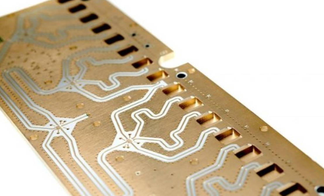
The most common and effective method for making aluminum suitable for high frequencies is creating a hybrid stack-up using industry-standard high-frequency laminates, such as Rogers RO4350B, RO4003C, or advanced PTFE (Teflon) substrates. In this configuration, the high-frequency signal traces are etched onto the Rogers/PTFE laminate. This laminate is then bonded to an aluminum base plate using a highly specialized, thermally conductive prepreg or bonding film.
Because the high-frequency signals only travel through the top copper traces and interact solely with the low-loss, stable-Dk Rogers laminate, signal integrity remains perfectly intact. The aluminum base sits safely below, acting purely as a heavy-duty heat sink and structural support. This hybrid architecture completely circumvents the high dissipation factor and unstable dielectric constant of traditional MCPCBs, allowing for flawless operation well into the high gigahertz frequencies, including millimeter-wave applications for 5G.
Advanced Thermally Conductive Dielectrics for RF
In addition to hybrid bonding, material science has advanced to create specialized prepregs that bridge the gap between thermal and electrical performance. Certain manufacturers have developed proprietary laminate systems formulated specifically for high-power RF applications. These advanced dielectrics utilize carefully engineered ceramic fillers blended with low-loss hydrocarbon resins or PTFE.
These specialized materials achieve a highly stable dielectric constant across a wide temperature spectrum and maintain a very low dissipation factor (often below 0.003), while offering thermal conductivities significantly higher than standard FR4. While they may not match the extreme thermal transfer rates of standard LED-focused aluminum PCBs, they provide a sufficient thermal pathway to the aluminum base without destroying the RF signal. These advanced dielectrics enable strict impedance control and allow designers to create wider traces capable of handling higher RF currents.
Key Benefits of Aluminum Base in High-Power RF Applications
Once the dielectric limitations are overcome via hybrid stack-ups or advanced RF materials, the inclusion of an aluminum base plate offers transformative benefits for high-frequency circuitry. High-power RF components are notoriously difficult to cool, and traditional cooling methods often add unacceptable bulk or complexity to the system.
Integrating the heat sink directly into the PCB substrate simplifies the mechanical design and drastically improves reliability. The benefits extend beyond mere temperature control, influencing the mechanical durability and electromagnetic compatibility (EMC) of the final product.
Unmatched Thermal Management
High-frequency power amplifiers (such as GaN or GaAs transistors) used in base stations and radar systems generate intense localized heat. If this heat is not rapidly dissipated, the junction temperature of the semiconductor rises, leading to thermal runaway, reduced efficiency, and premature component failure. Even slight increases in operating temperature can shift the operating frequency of delicate RF oscillators.
An aluminum base provides a massive, continuous thermal plane. Compared to standard FR4 boards that rely on thermal vias to transfer heat to a separate heatsink, a hybrid aluminum PCB offers an incredibly low thermal resistance path. The heat spreads laterally across the metal core and is efficiently radiated away or transferred to an external chassis. This robust thermal management ensures that the RF components operate within their ideal temperature windows, maintaining signal stability and extending the lifespan of the device.
Mechanical Stability and Electromagnetic Shielding
High-frequency laminates, particularly PTFE-based materials, are notoriously soft and prone to dimensional changes under thermal stress. This dimensional instability can alter the physical dimensions of precisely tuned microstrip lines, negatively impacting the circuit’s resonant frequency. Bonding these soft RF laminates to a rigid aluminum core provides immense mechanical stability, ensuring that trace geometries remain static regardless of temperature fluctuations or physical vibration.
Furthermore, the solid aluminum backing acts as a highly effective electromagnetic shield. In complex RF systems, cross-talk and electromagnetic interference (EMI) can severely degrade performance. The grounded aluminum base forms a continuous shielding layer, preventing external electromagnetic fields from interfering with the sensitive traces above, and preventing the board’s own high-frequency signals from radiating downward into other sensitive electronics.
Comparing Aluminum PCBs with Other High-Frequency Materials
To fully grasp when to use a hybrid aluminum PCB, it is helpful to compare it against other common substrate choices in the PCB manufacturing industry. Different applications require different trade-offs between cost, thermal performance, and electrical integrity.
| Material Type | Dielectric Constant (Dk) Stability | Signal Loss (Df) | Thermal Conductivity (W/m·K) | Ideal Application |
|---|---|---|---|---|
| Standard FR4 | Poor at high frequencies | High (~0.020) | Low (~0.25) | Low frequency, low power general electronics. |
| Standard Aluminum PCB | Very Poor / Unstable | High (>0.015) | High (1.0 – 5.0+) | LED lighting, power supplies, motor controllers. |
| Pure Rogers / PTFE | Excellent / Highly Stable | Very Low (<0.003) | Low to Moderate (~0.5 – 1.0) | High-frequency telecom, radar, low-power RF. |
| Hybrid (Rogers + Aluminum) | Excellent (Top Layer) | Very Low (Top Layer) | High (Base Layer) | High-power RF amplifiers, 5G base stations. |
As the table illustrates, a hybrid setup perfectly bridges the gap. While a pure Rogers board is excellent for RF, it struggles with extreme heat. Standard aluminum excels at heat but destroys RF signals. The hybrid structure is the optimal solution for high-power, high-frequency environments, albeit at a higher manufacturing cost.
Best Practices for Designing High-Frequency Metal Core PCBs
Designing a high-frequency circuit on an aluminum-backed board requires a different approach than standard FR4 design. Engineers must account for both the RF characteristics of the top laminate and the unique manufacturing constraints of a metal-backed board.
First, grounding is paramount. In high-frequency design, establishing a solid, continuous return path is critical. When using an aluminum base, designers must carefully plan how the top copper ground plane connects to the aluminum backing. This is often achieved through specialized plated through-holes (PTH). However, plating a via through a solid aluminum block risks short-circuiting the signal to the metal core. Manufacturers use a process called “resin plugging” or “isolated vias,” where they drill a larger hole in the aluminum, fill it with non-conductive epoxy, and then drill and plate a smaller via through the center of the epoxy.
Secondly, careful stack-up planning is required. Designers must specify the exact high-frequency laminate (e.g., 10-mil Rogers 4350B) and ensure that the manufacturer uses a low-loss bonding film to adhere it to the aluminum. The thickness of the high-frequency laminate must be chosen carefully to allow for manageable trace widths that achieve the target 50-ohm or 75-ohm impedance without becoming too narrow to carry the required power.
Conclusion: Final Verdict on Aluminum PCBs for High Frequencies
In conclusion, the question of whether an aluminum PCB is suitable for high-frequency circuits depends entirely on the dielectric material separating the copper from the metal core. Standard, off-the-shelf aluminum PCBs equipped with thermal epoxy dielectrics are entirely unsuitable for high-frequency applications due to massive signal attenuation, erratic impedance, and high parasitic capacitance.
However, through advanced manufacturing techniques, hybrid aluminum PCBs represent a pinnacle of modern circuit board engineering. By bonding low-loss, stable-Dk laminates like Rogers or PTFE to a rigid, thermally conductive aluminum base, designers can achieve unparalleled performance. This configuration safely dissipates the intense heat generated by high-power solid-state amplifiers while preserving the pristine signal integrity required for modern 5G, aerospace, and microwave communications. For applications demanding extreme thermal management alongside high-frequency operation, high-frequency aluminum PCBs are not just suitable—they are heavily recommended.