1. Introduction: The Critical Choice for Advanced Electronics
In the relentless march of technological progress, the demands placed on electronic components are escalating at an unprecedented rate. From lightning-fast 5G networks to sophisticated automotive radar systems, the underlying printed circuit board (PCB) is no longer a passive substrate but a critical determinant of overall system performance and reliability. As frequencies climb, data rates surge, and power densities increase, the limitations of traditional PCB materials become starkly apparent. This necessitates a more discerning approach to material selection, a decision that profoundly impacts signal integrity, thermal management, and ultimately, the success of your high-performance electronic designs.
This guide delves into the fundamental differences between Rogers PCB materials and the ubiquitous FR4, shedding light on why the former has become the go-to solution for cutting-edge applications. We’ll explore their respective properties, highlight their strengths and weaknesses, and provide the insights necessary for engineers, product developers, and procurement specialists to make informed decisions that elevate their next-generation electronics.

2. Understanding FR4: The Industry Workhorse (and Its Limitations)
FR4, or Flame Retardant Level 4, is the undisputed workhorse of the PCB industry. Its widespread adoption stems from its fiberglass fabric reinforcement impregnated with an epoxy resin binder. This composition offers a good balance of electrical, mechanical, and thermal properties at a remarkably cost-effective price point, making it suitable for a vast array of general-purpose electronic applications, from consumer gadgets to industrial controls.
2.1 FR4 Basics: Composition and Common Applications
FR4’s structure, a woven fiberglass cloth infused with epoxy resin, provides mechanical strength and insulation. Its ease of manufacturing, including drilling, etching, and soldering, contributes significantly to its popularity. You’ll find FR4 in virtually every electronic device around you, from your smartphone to your washing machine, serving as the foundation for countless circuit boards where high-frequency performance isn’t the primary concern.
2.2 Key Properties of FR4
While versatile, FR4’s properties exhibit certain characteristics that can become problematic in high-performance scenarios:
- Dielectric Constant (Dk): Typically ranging from 4.3 to 4.7, FR4’s Dk is not very stable across different frequencies or temperatures. This variability can lead to impedance mismatches and signal distortion, particularly as operating frequencies increase.
- Dissipation Factor (Df): Also known as loss tangent, FR4’s Df is relatively high (around 0.018 to 0.025 at 1 GHz). A higher Df means more signal energy is converted into heat, resulting in signal loss and a reduction in power efficiency, especially at higher frequencies.
- Thermal Performance: FR4 has a glass transition temperature (Tg) typically between 130°C and 180°C. Above this temperature, the material softens, and its properties degrade. Its Coefficient of Thermal Expansion (CTE) is also significantly higher than that of copper, which can cause stress on vias and solder joints during thermal cycling, leading to reliability issues.
- Moisture Absorption: FR4 is somewhat susceptible to moisture absorption, which can alter its electrical properties and even cause delamination over time, particularly in humid environments.
- Cost-Effectiveness and Manufacturability: These are FR4’s undeniable strengths. Its mature manufacturing processes and readily available materials contribute to its low cost, making it the default choice for budget-conscious designs.
2.3 When FR4 Falls Short
Despite its merits, FR4 reaches its limits when applications demand extreme precision and reliability. For high-frequency (RF/microwave), high-speed digital, and high-power applications, FR4’s inherent limitations in Dk stability, Df, and thermal management can lead to significant performance degradation, increased signal loss, and even system failure. This is where the specialized properties of Rogers materials become not just advantageous, but essential.
3. Delving into Rogers PCB: The High-Performance Solution
Rogers Corporation is a renowned name in advanced materials, particularly for high-frequency and high-speed applications. Their specialized laminates, often referred to as Rogers PCB materials, are engineered to overcome the deficiencies of FR4, offering superior electrical, thermal, and mechanical stability.
3.1 What Makes Rogers Different? Composition and Material Families
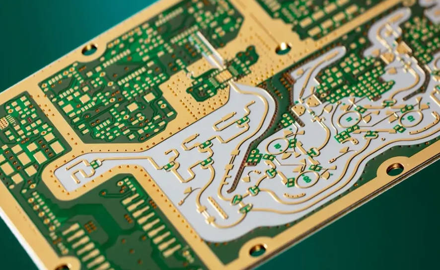
Unlike FR4’s epoxy-fiberglass composition, Rogers materials typically utilize advanced PTFE (polytetrafluoroethylene, often known by the DuPont brand Teflon) or ceramic-filled hydrocarbon thermoset resins. This fundamental difference in chemistry is the key to their superior performance. Rogers offers various material families, each tailored for specific performance requirements:
- RO4000 Series: Ceramic-filled hydrocarbon thermosets, offering excellent high-frequency performance with processing similar to FR4. They are often chosen for their balance of performance and relatively lower Rogers PCB cost compared to pure PTFE laminates.
- RO3000 Series: PTFE-based laminates with ceramic fillers, known for their outstanding electrical stability over a wide range of frequencies and temperatures.
- RT/duroid Series: High-performance PTFE laminates, often glass microfiber or ceramic-filled, providing the best electrical performance for the most demanding RF and microwave applications.
3.2 Superior Electrical Properties
The hallmark of Rogers materials is their exceptional electrical performance, making them ideal for signal integrity-critical designs.
- Stable Dielectric Constant (Dk): Rogers laminates boast a very low and stable Dk (ranging from ~2.2 to ~11), with minimal variation across wide frequency ranges and temperatures. This stability is paramount for maintaining consistent impedance and predictable signal propagation, crucial for precise timing and minimal signal distortion in high-speed digital and RF circuits.
- Low Dissipation Factor (Df): With significantly lower Df values (typically 0.001 to 0.009), Rogers materials exhibit minimal signal loss. This translates to higher power efficiency and better signal fidelity, especially critical for high-frequency transmissions where every decibel of loss matters.
- Reduced Dispersion: Rogers materials exhibit less dispersion, meaning that different frequency components of a signal travel at more consistent speeds. This is vital for maintaining waveform integrity in high-speed digital signals and complex RF modulated signals.
3.3 Excellent Thermal Management
High-performance applications often generate substantial heat. Rogers materials excel in thermal management:
- Low CTE: Rogers materials have a Coefficient of Thermal Expansion (CTE) that closely matches that of copper. This minimizes stress on plated through-holes (vias) and solder joints during thermal cycling, significantly enhancing the long-term reliability and durability of the PCB, especially in demanding environments.
- Higher Thermal Conductivity: Many Rogers materials possess superior thermal conductivity compared to FR4. This enables more efficient dissipation of heat away from active components, preventing hotspots and contributing to overall system stability and lifespan.
3.4 Moisture Resistance
Due to their low moisture absorption rates, Rogers laminates maintain their electrical properties even in humid conditions. This resistance is critical for outdoor equipment, medical devices, and other applications exposed to varying environmental moisture levels.
3.5 Manufacturing Considerations for Rogers Materials
While offering superior performance, working with Rogers materials requires specialized knowledge and equipment. Reputable Rogers PCB manufacturers understand the nuances of these materials.
- Specialized Fabrication Processes: Drilling Rogers laminates often requires specific drill bits and parameters to prevent smearing (especially for PTFE-based materials). Lamination cycles, etching chemistries, and surface finishes also need to be optimized for Rogers materials.
- Material Handling: Rogers laminates can be softer or more flexible than FR4, requiring careful handling to prevent damage or warping during fabrication.
- Panel Utilization: Due to their higher material cost, optimizing panel utilization and minimizing waste is crucial for managing overall Rogers PCB cost.
3.6 Cost Implications of Rogers Materials
The advanced chemistry and specialized manufacturing processes translate into a higher Rogers PCB cost per square inch compared to FR4. However, this initial investment is often justified by:
- Superior Performance: Enabling functionalities and achieving performance levels simply impossible with FR4.
- Reduced Development Time: Less time spent debugging signal integrity issues.
- Enhanced Reliability: Leading to longer product lifecycles and fewer field failures.
- Competitive Advantage: Delivering products with superior specifications to the market.
4. Direct Comparison: Rogers vs. FR4 in Key Performance Areas
Let’s put Rogers and FR4 head-to-head across critical performance metrics:
| Property | FR4 | Rogers PCB Materials | Impact on Performance |
| Dielectric Constant (Dk) | 4.3 – 4.7 (Variable with Freq/Temp) | 2.2 – 11 (Stable, Low Variation) | Stability is crucial for consistent impedance and signal fidelity at high frequencies. Less signal distortion. |
| Dissipation Factor (Df) | 0.018 – 0.025 (Higher Loss) | 0.001 – 0.009 (Lower Loss) | Lower Df means significantly less signal loss and heat generation, vital for RF/microwave. |
| Frequency Range | Up to a few GHz (with limitations) | Tens of GHz and beyond | Enables designs for 5G, radar, satellite comms, high-speed data. |
| Thermal Conductivity | Low | Moderate to High | Better heat dissipation, preventing hotspots in power applications. |
| CTE (Z-axis) | High (150-300 ppm/°C above Tg) | Low, matches copper (10-30 ppm/°C) | Minimizes stress on vias and solder joints, improving long-term reliability. |
| Moisture Absorption | Moderate | Very Low | Maintains electrical performance in humid environments. |
| Cost | Low | Higher | Trade-off between initial investment and long-term performance/reliability. |
| Manufacturability | Easy, widely available processes | Requires specialized processes and expertise | Requires partnering with an experienced Rogers PCB manufacturer. |
4.1 Signal Integrity and Loss
For high-speed digital and RF applications, signal integrity is paramount. FR4’s higher Df and unstable Dk lead to significant insertion loss, especially as frequencies increase. Signals degrade, rise times are affected, and eye diagrams close, making reliable data transmission challenging. Rogers materials, with their low and stable Dk and significantly lower Df, minimize signal attenuation and dispersion, ensuring clean, high-fidelity signal transmission even at tens of gigahertz. This translates directly to better impedance control, reduced crosstalk, and ultimately, higher system performance.
4.2 Thermal Reliability and Power Handling
In power amplifiers, high-frequency circuits, and devices with dense component placement, heat generation is a major concern. FR4’s lower thermal conductivity can lead to hot spots, reducing component lifespan and overall system stability. Rogers materials’ superior thermal conductivity and CTE matched to copper make them ideal for managing heat effectively. This is crucial for high-power applications, ensuring components operate within their safe temperature limits and extending the lifespan of the entire system.
4.3 Mechanical Stability and Environmental Robustness
The thermal expansion mismatch between FR4 and copper can cause stress on vias and solder joints during repeated thermal cycling, leading to fractures and intermittent failures. Rogers materials’ low and matched CTE to copper significantly improves the mechanical stability and reliability of the PCB, particularly in applications subjected to wide temperature fluctuations or harsh environmental conditions. Their low moisture absorption also adds to their robustness in humid or wet environments.
4.4 Design Complexity and Manufacturability
Designing with Rogers materials requires a deeper understanding of their properties. Achieving precise impedance control is more straightforward due to the stable Dk. However, the fabrication process is more specialized. Drilling through PTFE-based laminates, for instance, requires specific tooling and speeds to prevent smearing. Working with a knowledgeable Rogers PCB design team and an experienced Rogers PCB manufacturer is crucial to ensure successful fabrication and optimal performance.
4.5 Cost-Benefit Analysis
While the raw material cost of Rogers laminates is higher, the total cost of ownership for a high-performance system often favors Rogers. The initial material premium can be offset by:
- Reduced Development Cycles: Less time spent on debugging signal integrity issues.
- Improved Product Performance: Meeting stringent specifications and gaining a competitive edge.
- Enhanced Reliability and Lifespan: Fewer field failures, reduced warranty claims, and higher customer satisfaction.
- Miniaturization: Superior electrical properties can sometimes enable more compact designs, saving space and other material costs.
5. Common Use Cases for Rogers PCB (Where FR4 Won’t Cut It)
The superior properties of Rogers materials make them indispensable for applications where FR4 simply cannot meet the performance requirements:
- RF and Microwave Applications: This is arguably the primary domain for Rogers. Think of base station antennas, power amplifiers (PAs), low noise amplifiers (LNAs), filters, couplers, and mixers for 5G/6G infrastructure, satellite communication systems, and radar. Their low loss and stable Dk are critical for precise impedance matching and minimal signal degradation.
- High-Speed Digital Circuits: For data rates exceeding 10 Gbps (and certainly for 25 Gbps, 50 Gbps, and beyond), FR4 struggles with signal integrity. Rogers materials are essential for server backplanes, high-speed data interconnects, network switches, and test & measurement equipment where clean eye diagrams and low bit error rates are paramount.
- Automotive Radar and ADAS Systems: The burgeoning field of autonomous driving relies heavily on radar sensors. These require robust, high-frequency PCBs that can withstand harsh automotive environments (temperature extremes, vibration, moisture) while delivering precise signal performance.
- Aerospace and Defense: Applications like avionics, airborne radar, electronic warfare systems, and space-grade communication modules demand extreme reliability, lightweight solutions, and uncompromised performance in challenging conditions. Custom Rogers PCB solutions are frequently developed for these specialized needs.
- Medical Devices: High-precision medical imaging equipment (e.g., MRI coils, ultrasound transducers) and advanced diagnostic tools often utilize Rogers materials for their electrical stability and reliability in sensitive applications.
6. Addressing Your FAQs About Rogers PCB
When considering Rogers materials, several common questions arise for designers and procurement teams:
- “Is Rogers PCB always better than FR4?” No, not always. For general-purpose, lower-frequency applications where cost is the primary driver, FR4 remains the most economical and perfectly adequate choice. Rogers materials are a specialized solution for applications where FR4’s limitations become performance bottlenecks.
- “How much more expensive is Rogers PCB?” The cost difference varies significantly based on the specific Rogers material type, board complexity, layer count, and order volume. Generally, Rogers PCB cost can range from 3 to 10 times (or even more for highly specialized variants) the cost of an equivalent FR4 board. However, this initial material cost is often offset by superior performance, reduced debugging, and increased product lifespan. When obtaining quotes, ensure you’re working with a reputable Rogers PCB supplier who can provide accurate pricing for your specific needs.
- “Can I mix Rogers and FR4 in the same design?” Yes, hybrid stack-ups are common. This approach involves using Rogers materials for critical RF or high-speed layers and FR4 for less sensitive layers (e.g., power planes, low-speed control signals). This can be a strategic way to optimize Rogers PCB cost while still achieving critical performance goals. However, careful consideration of material compatibility, thermal expansion differences at the interface, and manufacturing processes is essential.
- “What are the common challenges in designing with Rogers materials?” Challenges primarily revolve around precise impedance control due to the thinner laminates, specialized drilling and routing requirements (especially for PTFE-based materials), and managing the slightly higher material cost. Proper Rogers PCB design guidelines are crucial.
- “How do I choose the right Rogers material for my specific application?” Selecting the correct Rogers material involves considering several key factors:
- Operating Frequency: The primary driver for Dk and Df requirements.
- Power Handling: Impacts thermal conductivity and CTE matching.
- Temperature Range: Affects Dk and Df stability, and CTE considerations.
- Environmental Conditions: Moisture resistance, thermal cycling.
- Cost vs. Performance Trade-off: Balancing budget with technical requirements.
- Manufacturing Feasibility: Ensuring your chosen Rogers PCB manufacturer has the capabilities for the specific material.
7. Conclusion: Making an Informed Material Decision
The choice between Rogers PCB materials and FR4 is a pivotal decision in the development of any electronic product. While FR4 remains an excellent and economical choice for a vast array of general-purpose applications, the escalating demands of modern high-performance electronics increasingly necessitate the superior characteristics of Rogers laminates.
For applications where signal integrity, minimal loss, excellent thermal management, and long-term reliability in challenging environments are paramount, investing in Rogers PCB technology is not merely an option, but a necessity. Their stable dielectric constant, low dissipation factor, and matched thermal expansion properties empower engineers to design circuits that can achieve unparalleled performance in high-frequency, high-speed, and high-power domains.To ensure the successful realization of your high-performance designs, it is vital to partner with an experienced Rogers PCB manufacturer and a reliable Rogers PCB supplier who possess the expertise and specialized equipment required to handle these advanced materials. They can provide invaluable guidance on Rogers PCB design best practices, material selection, and ultimately, deliver custom Rogers PCB solutions that meet your exact specifications and performance targets. By making an informed material decision, you not only optimize your product’s performance but also enhance its reliability, reduce long-term costs, and gain a significant competitive edge in today’s demanding electronics market.


