
Table-of-contents
- Introduction: The Foundation of Modern Electronics
- Material Overviews: The Building Blocks of High-Speed Performance
- Detailed Property Comparisons: A Quantitative Analysis
- Applications and Use Cases: Where Each Material Shines
- Selection Guide: Answering Your High-Speed PCB Questions
- Conclusion: Making the Right Choice for Your Design
1. Introduction: The Foundation of Modern Electronics
In the relentless evolution of electronics, the demand for faster data transmission, higher frequencies, and more compact devices has pushed the boundaries of traditional circuit board technology. This has given rise to the critical field of high-speed Printed Circuit Boards (PCBs). A PCB is generally considered “high-speed” when the integrity of the signals it carries becomes significantly affected by the physical characteristics of the board itself, such as its layout, packaging, and material properties. This typically occurs at signal frequencies above 500 MHz, but the definition is also dependent on the signal’s rise time and the electrical length of the traces. These advanced circuits are the silent workhorses behind the technologies that define our modern world, from the lightning-fast networks of 5G and 6G telecommunications to the sophisticated radar systems in autonomous vehicles, and the mission-critical electronics in aerospace and defense.
The selection of the right substrate material is arguably one of the most critical decisions in high-speed PCB design. It’s a choice that directly impacts signal integrity, thermal management, and the overall reliability and performance of the final product. For engineers and designers, this decision process is a complex balancing act. Key concerns often revolve around several pivotal questions:
- How can we balance the high cost of specialized materials with the required performance benchmarks?
- What is the most effective way to minimize signal loss and distortion as frequencies climb into the gigahertz range?
- How do we efficiently handle heat dissipation in increasingly power-dense and compact designs?
- Which material is best suited for a specific operating frequency and environment?
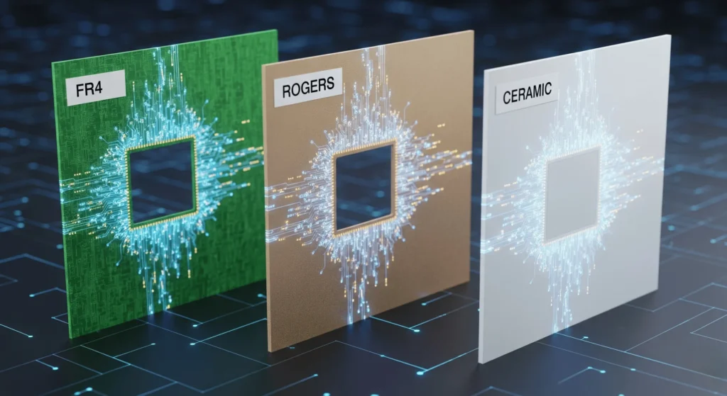
This article aims to provide a professional, in-depth comparison of three of the most prominent material categories used in high-speed PCB manufacturing: FR4, Rogers, and Ceramic substrates. FR4 (Flame Retardant 4) is the ubiquitous, cost-effective standard, an epoxy-based laminate that serves as the backbone of a vast majority of consumer and industrial electronics. Rogers materials are a class of high-performance, laminate-based substrates engineered specifically for the demanding requirements of RF and microwave applications. Ceramic substrates represent the pinnacle of performance for high-power, high-frequency designs operating in the most extreme environments. By dissecting their compositions, comparing their critical properties, and exploring their ideal applications, this guide will equip you with the knowledge needed to make informed decisions for your next high-speed design challenge.
2. Material Overviews: The Building Blocks of High-Speed Performance
FR4 (Flame Retardant 4)
Composition: FR4 is a composite material composed of woven fiberglass cloth reinforced with an epoxy resin binder. This structure gives it a good balance of mechanical strength, electrical insulation, and manufacturability. The “FR” designation indicates that it meets the UL94V-0 standard for flame retardancy, a crucial safety requirement for most electronic applications.
Key Characteristics: The primary appeal of FR4 lies in its exceptional cost-effectiveness and widespread availability. Decades of use have refined its manufacturing processes, making it the default choice for general-purpose and low-to-mid-frequency PCBs. It is easy to drill, mill, and process, allowing for high-volume production with excellent yields.
Limitations in High-Speed Contexts: Despite its popularity, FR4 begins to show its limitations as signal speeds and frequencies increase. Its most significant drawbacks in high-speed applications are its relatively high dielectric loss (dissipation factor) and a dielectric constant that varies significantly with frequency. Furthermore, FR4 has higher moisture absorption, which can alter its electrical properties and negatively impact performance in humid environments. These factors can lead to unacceptable signal degradation, impedance mismatches, and overall loss of signal integrity in demanding high-speed circuits.
Rogers Materials
Composition: Rogers materials are a family of high-performance laminates, distinct from FR4 in their specialized composition. They are typically made from ceramic-filled Polytetrafluoroethylene (PTFE) or hydrocarbon-based thermoset resins. Popular series like the RO4000® family use woven glass-reinforced hydrocarbon/ceramic composites, offering a blend of performance and ease of fabrication that is superior to traditional PTFE materials.
Key Characteristics: Rogers materials are engineered from the ground up for high-frequency stability. Their defining features are a very low dissipation factor (Df) and a stable dielectric constant (Dk) across a wide range of frequencies. This consistency is vital for maintaining controlled impedance and minimizing signal loss in sensitive RF and microwave circuits. They also exhibit excellent dimensional stability and low Z-axis thermal expansion, which enhances the reliability of plated through-holes in multilayer board designs.
Advantages: The controlled dielectric properties of Rogers materials make them the superior choice for high-frequency applications. They are the go-to solution for RF antennas, power amplifiers, satellite communication systems, and automotive radar sensors where preserving the purity and strength of the signal is paramount.
Ceramic Substrates
Composition: Ceramic substrates are crafted from inorganic, non-metallic materials, most commonly Alumina (Aluminum Oxide, ) and Aluminum Nitride (AlN). Beryllium Oxide (BeO) is also used for its exceptional thermal properties, though its use is limited due to toxicity concerns. These materials are often combined with metal cores or integrated into complex packages like High-Temperature Co-fired Ceramic (HTCC) or Low-Temperature Co-fired Ceramic (LTCC) to create robust, multilayer modules.
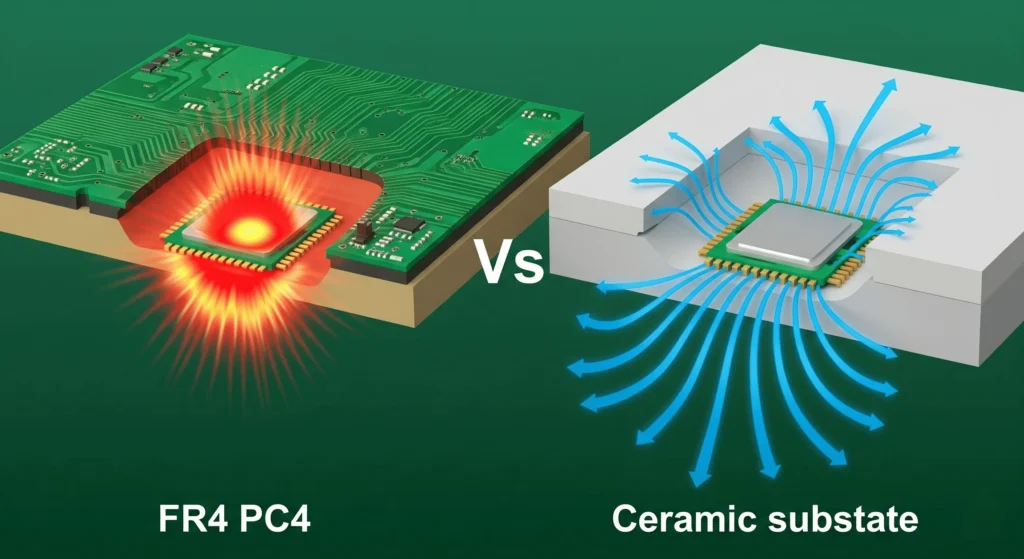
Key Characteristics: The hallmark of ceramic substrates is their exceptional thermal conductivity, which is orders of magnitude higher than that of FR4 and significantly better than Rogers materials. This allows them to dissipate heat with extreme efficiency. They also provide excellent electrical insulation and can maintain their properties at very high operating temperatures.
Advantages: The combination of superior thermal management and high-frequency electrical performance makes ceramic substrates ideal for the most demanding applications. They are the preferred choice for high-power RF devices, power electronics modules, high-brightness LEDs, and any scenario where high power density and harsh environmental conditions converge. Their near-zero moisture absorption and hermetic sealing capabilities ensure reliability in mission-critical aerospace, defense, and medical applications.
3. Detailed Property Comparisons: A Quantitative Analysis
Choosing the right high-speed PCB material requires a deep understanding of its electrical, thermal, and mechanical properties. A seemingly small difference in a parameter like the dissipation factor can have a cascading effect on the performance of a multi-gigabit data channel.
Electrical Properties
The electrical performance of a substrate is the most critical factor for ensuring signal integrity in high-speed designs. The three key parameters are the dielectric constant (Dk), the dissipation factor (Df), and the overall frequency response.
| Property | FR4 (High-Performance) | Rogers (RO4350B) | Ceramic (Alumina 96%) | Significance in High-Speed Design |
|---|---|---|---|---|
| Dielectric Constant (Dk) | 3.4 – 4.8 (Varies with freq.) | 3.48 ± 0.05 (Stable) | 9.8 (Stable) | Determines signal propagation speed and impedance. Stability is key for predictable performance. |
| Dissipation Factor (Df) | 0.012 – 0.020 | 0.0037 @ 10 GHz | ~0.0001 – 0.001 | Measures signal energy lost as heat. Lower is better, crucial for minimizing attenuation at high frequencies. |
| Volume Resistivity (Ω-cm) | 106−1010 | >1010 | >1014 | Indicates the material’s ability to insulate and prevent current leakage between traces. |
Dielectric Constant (Dk): This property influences the speed at which a signal travels along a trace and is fundamental to calculating the characteristic impedance of a transmission line. While FR4 has a Dk in a similar range to some Rogers materials, its value can fluctuate significantly with changes in frequency. This instability makes it difficult to maintain tight impedance control (e.g., 50 Ω) across a broad spectrum. Rogers and Ceramic materials, in contrast, offer a highly stable Dk across their specified frequency ranges, ensuring predictable signal behavior and minimizing reflections caused by impedance mismatches.
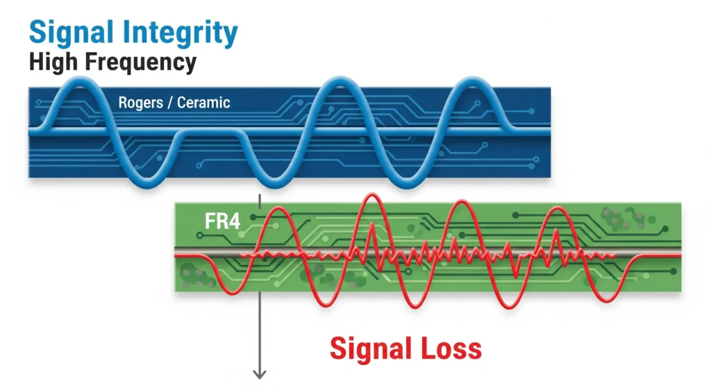
Dissipation Factor (Df / Loss Tangent): The dissipation factor quantifies how much of a signal’s electromagnetic energy is absorbed by the dielectric material and converted into heat. At frequencies above 1 GHz, FR4’s higher Df leads to significant signal attenuation, effectively weakening the signal as it travels. For data rates exceeding 10 Gbps or in RF applications, this loss can corrupt the signal beyond recovery. Rogers materials, with their exceptionally low Df, are engineered to preserve signal energy, making them essential for long trace lengths and high-frequency applications where signal integrity is non-negotiable. Ceramic substrates offer an even lower loss tangent, making them suitable for demanding mmWave applications.
Signal Integrity and Frequency Response: The combination of a stable Dk and a low Df gives Rogers and Ceramic materials a far superior frequency response compared to FR4. They enable cleaner signal transmission with less crosstalk, jitter, and skew, which are critical for high-speed digital circuits and phase-sensitive RF systems. While advanced “high-speed” FR4 variants have improved properties, they still cannot match the performance of specialized substrates for applications operating well into the multi-gigahertz range.
Thermal Properties
As component density and power levels increase, effective thermal management becomes just as important as electrical performance. An overheating PCB can lead to signal degradation, component failure, and reduced product lifespan.
| Property | FR4 (High-Tg) | Rogers (RO4350B) | Ceramic (AlN) | Significance in High-Speed Design |
|---|---|---|---|---|
| Thermal Conductivity (W/mK) | 0.3 – 0.4 | 0.69 | 170 – 280 | Measures the ability to conduct heat away from components. Higher is better for power-dense designs. |
| Glass Transition Temp (Tg °C) | 170 – 180 | >280 (No Tg) | >1000 | The temperature at which the material changes from a rigid to a deformable state. A higher Tg indicates better thermal stability. |
| CTE (ppm/°C, Z-axis) | 50 – 60 | 50 | 4.6 | Coefficient of Thermal Expansion. A low Z-axis CTE is crucial for via reliability during thermal cycling. |
Thermal Conductivity: This is the most telling metric for heat dissipation. Ceramic substrates, particularly Aluminum Nitride (AlN), are in a class of their own, offering thermal conductivity that rivals some metals. This allows them to act as an integrated heat sink, efficiently pulling heat away from powerful components like processors, FPGAs, and power amplifiers. Rogers materials offer a modest improvement over FR4, providing better heat spreading for mid-power applications. FR4’s low thermal conductivity makes it a bottleneck for heat removal, risking component failure in high-power scenarios.
Glass Transition Temperature (Tg) and CTE: Tg represents the temperature at which the epoxy in FR4 softens. Operating near or above Tg can cause delamination and compromise the board’s structural integrity. High-Tg FR4 variants offer improved performance, but Rogers and Ceramic materials are far more stable at elevated temperatures. The Coefficient of Thermal Expansion (CTE), especially in the Z-axis, is critical for the reliability of plated through-holes (vias) in multilayer boards. A large mismatch between the CTE of the copper plating and the substrate material can cause vias to crack or fail during thermal cycling. Rogers materials are engineered to have a low CTE that closely matches copper, enhancing long-term reliability.
Mechanical and Environmental Properties
The physical durability and stability of a PCB in its operating environment are crucial for long-term performance.
| Property | FR4 | Rogers | Ceramic (Alumina) | Significance in High-Speed Design |
|---|---|---|---|---|
| Rigidity / Brittleness | Good flexibility, robust | More rigid than FR4 | Very high strength, but brittle | Affects handling during assembly and resistance to shock and vibration. |
| Moisture Absorption (%) | 0.10 – 0.25 | < 0.06 | ~0.00 | High absorption can alter electrical properties, especially Dk, leading to performance drift. |
| Fabrication Complexity | Standard, easy to process | Specialized lamination | Firing, laser drilling, complex | Impacts manufacturing cost, yield, and lead times. |
Rigidity and Brittleness: FR4 is known for its durability and relative flexibility, making it easy to handle and fabricate without special precautions. Rogers materials are generally more rigid. Ceramic, while possessing very high compressive strength, is brittle and can fracture under mechanical stress or shock if not properly supported and housed. This requires careful consideration in the mechanical design of the end product.
Moisture Absorption: This is a critical but often overlooked property. FR4’s tendency to absorb moisture from the air can cause its Dk value to drift, leading to inconsistent performance, especially in humid environments. Rogers and Ceramic substrates have extremely low moisture absorption rates, ensuring their electrical properties remain stable and predictable regardless of ambient humidity. This makes them ideal for applications in avionics, marine systems, and outdoor telecommunications equipment.
Cost and Manufacturing Considerations
Ultimately, the choice of material must be justified by the application’s budget and manufacturing capabilities.
| Material | Relative Pricing ($/sq. inch) | Key Fabrication Challenges | Return on Investment (ROI) |
|---|---|---|---|
| FR4 | $0.10 – $0.50 | Standard, scalable, well-understood processes. | Excellent for prototypes, consumer products, and low-to-mid frequency applications where cost is a primary driver. |
| Rogers | $5.00 – $20.00 | Requires specialized lamination cycles, plasma desmear for vias, and careful handling. Higher risk of yield loss. | Justified for high-performance RF/microwave and high-speed digital systems where signal integrity is paramount and outweighs the material cost. |
| Ceramic | $2.00 – $10.00+ | Involves high-temperature firing processes, laser drilling for vias, and complex multilayer co-firing techniques. Longer lead times. | Essential for high-power, high-reliability applications in harsh environments. The cost is justified by thermal performance and longevity. |
The cost differential is significant. FR4 is an order of magnitude cheaper than Rogers materials, making it the only viable choice for many mass-market products. The manufacturing processes for Rogers and Ceramic are more complex and less forgiving, requiring specialized equipment and expertise. This not only increases the upfront cost but can also lead to longer lead times and potentially lower manufacturing yields. Therefore, the decision to use a premium material like Rogers or Ceramic is an investment in performance and reliability, justified when the application’s failure would be catastrophic or its performance is directly tied to revenue (as in telecommunications infrastructure).
4. Applications and Use Cases: Where Each Material Shines
The theoretical properties of a material only become meaningful when applied to real-world scenarios. Each substrate has carved out a niche where its unique profile of cost and performance provides the optimal solution.
FR4 in High-Speed Contexts
While often labeled as a “low-speed” material, high-performance grades of FR4 are perfectly suitable for a wide range of “high-speed” digital applications. You will find it in:
- Consumer Electronics: Motherboards, graphics cards, and solid-state drives (SSDs) where data rates are high but trace lengths are short, and cost is a major factor.
- Automotive ECUs: Engine control units and infotainment systems that operate at moderate frequencies (typically up to 500 MHz) and do not require the ultra-low loss of more expensive materials.
- Industrial Control Systems: Where digital logic and control signals need reliable transmission, but the environment and frequency do not justify the cost of RF-grade substrates.
FR4’s limitations become apparent when moving into the RF domain or when dealing with very high data rates (>10-15 Gbps) over longer distances, where its inherent signal loss becomes a crippling factor.
Rogers Applications
Rogers materials are the industry standard for applications where the purity of high-frequency signals is critical. Their use is widespread in:
- RF Antennas and Base Stations: For 4G, 5G, and emerging 6G networks, Rogers materials ensure that signals are transmitted and received with minimal loss and distortion.
- Satellite and Aerospace Systems: In satellite communications, GPS receivers, and airborne radar, the stability and reliability of Rogers laminates are essential for mission-critical performance.
- ADAS Radar: Advanced Driver-Assistance Systems in modern vehicles rely on 77 GHz radar sensors built on Rogers substrates to accurately detect obstacles, making them a key component of automotive safety.
- High-Speed Digital Backplanes: For high-end servers and network routers transferring terabits of data, low-loss materials are necessary to maintain signal integrity across large circuit boards.
Ceramic Applications
Ceramic substrates are reserved for the most extreme applications where high power, high frequency, and high reliability are non-negotiable. Their primary domains include:
- High-Power LEDs: The excellent thermal conductivity of ceramic substrates is vital for dissipating heat from high-brightness LED arrays used in automotive headlights and industrial lighting.
- Power Amplifiers and Microwave Modules: In military radar, electronic warfare systems, and broadcast transmitters, ceramic packages can handle immense power loads while maintaining stable RF performance.
- Defense and Medical Electronics: In applications like phased-array radar or medical imaging equipment (MRI), the robustness and hermeticity of ceramic ensure performance in extreme temperatures and environments where failure is not an option.
- Electric Vehicles (EVs): Power inverter modules and battery management systems in EVs generate significant heat, making ceramic substrates an ideal choice for ensuring long-term reliability.
Hybrid Approaches
To optimize for both cost and performance, designers often employ hybrid PCB stackups. A common approach is to use a layer of Rogers material for the critical high-frequency signal traces on the outer layers, while using cheaper FR4 material for the inner power and ground planes. This creates a cost-effective board that delivers high performance where it’s needed most. Similarly, a ceramic core might be used to mount a high-power component, with the rest of the circuitry built on a more conventional laminate.
5. Selection Guide: Answering Your High-Speed PCB Questions
With a clear understanding of the materials, we can now formulate a decision-making framework to address the common questions faced by designers.
When to Choose FR4?
Choose FR4 for your high-speed design when:
- Cost is the primary constraint. For consumer products or large-volume manufacturing, the economic advantage of FR4 is often insurmountable.
- Operating frequencies are below 1 GHz. In this range, the dielectric losses of high-grade FR4 are often manageable.
- Signal paths are short. For small boards or chip-to-chip communication over a few inches, FR4 can often handle data rates up to 5-10 Gbps with careful design (e.g., proper routing, back-drilling).
- Power dissipation is low. If the components on your board do not generate significant heat, FR4’s limited thermal conductivity will not be a bottleneck.
When to Choose Rogers?
Choose a Rogers material when:
- Operating frequencies are in the RF/Microwave range (1 GHz – 100 GHz). This is their primary domain where low signal loss is essential.
- Signal integrity is paramount. For applications like high-speed data channels (>10 Gbps over distance), test equipment, or sensitive receivers, the clean signal transmission offered by Rogers is worth the investment.
- Impedance control must be precise and stable. The stable Dk of Rogers materials ensures predictable impedance across a wide range of operating conditions.
- The application requires high reliability in varying environmental conditions. Low moisture absorption and stable thermal properties ensure consistent performance.
When to Choose Ceramic?
Choose a Ceramic substrate when:
- The design involves high-power components. If you need to dissipate tens or hundreds of watts of heat from a small area, ceramic is the only viable option.
- The operating environment is extremely harsh. For applications exposed to very high temperatures, thermal shock, vibration, or requiring hermetic sealing, ceramic offers unmatched durability.
- The application operates at very high frequencies (mmWave) and requires the absolute lowest signal loss.
- Miniaturization is key. The ability to integrate passive components and create complex 3D structures in LTCC/HTCC packages allows for highly compact modules.
Trade-Offs and Decision Framework
| Metric | FR4 | Rogers | Ceramic |
|---|---|---|---|
| Frequency Range | Low (< 1 GHz) | High (1 – 100 GHz) | Very High (mmWave) |
| Signal Loss | High | Very Low | Extremely Low |
| Thermal Conductivity | Poor | Moderate | Excellent |
| Cost | Low | High | Very High |
| Manufacturability | Easy | Moderate | Difficult |
| Reliability | Good | Excellent | Superior |
Emerging Trends (2025 Outlook)
The field of high-speed materials is constantly evolving, driven by the demands of next-generation technologies:
- Advanced Hybrid Substrates: We will see more sophisticated hybrid materials that blend the properties of different polymers and fillers to achieve an optimal balance of cost, performance, and manufacturability, blurring the lines between traditional categories.
- Sustainability: There is a growing push for “green” electronics, leading to the development of halogen-free laminates and more environmentally friendly manufacturing processes.
- AI-Optimized Designs: Artificial intelligence and machine learning tools are beginning to play a role in material selection and PCB layout, running complex simulations to predict performance and recommend the most cost-effective material stackup for a given set of constraints.
- 5G/6G and IoT: The rollout of 5G and the development of 6G will continue to drive demand for low-loss materials that can perform at mmWave frequencies. The proliferation of IoT devices will require materials that are both low-cost and reliable in a wide range of environments.
FAQs
Q: Can FR4 really handle 10 Gbps data rates?
A: Yes, but with significant limitations. It is possible on short traces (a few inches) with aggressive signal integrity techniques like optimized routing, back-drilling vias to remove stubs, and using very smooth copper foils. However, for longer traces or backplanes, a low-loss material like Rogers is a much safer and more reliable choice.
Q: Is Rogers worth the high cost for prototypes?
A: Often, no. For initial functional prototypes where the goal is simply to verify logic and basic functionality, FR4 is usually sufficient and much more cost-effective. It’s better to invest in Rogers materials once the design is stable and you need to characterize its high-frequency performance or prepare for production.
Q: How can you mitigate the brittleness of Ceramic substrates?
A: Proper mechanical design is key. This includes mounting the ceramic substrate in a rugged housing, using appropriate underfill materials for components to absorb stress, and carefully controlling the manufacturing process to avoid introducing micro-fractures.
6. Conclusion: Making the Right Choice for Your Design
The journey through the world of high-speed PCB materials reveals a clear conclusion: there is no single “best” material. The optimal choice is a carefully considered compromise between performance requirements, environmental conditions, manufacturing capabilities, and budget.
FR4 remains the undisputed king of cost-efficiency, providing a “good enough” solution for a vast array of digital and lower-frequency applications.
Rogers materials provide the essential bridge to the world of high-frequency and high-speed digital, offering the low signal loss and stability that are indispensable for modern communications and computing.
Ceramic substrates stand as the ultimate solution for designs that push the limits of power and reliability in the most unforgiving environments.
As a final recommendation, always engage with your PCB fabricator early in the design process. They can provide invaluable guidance on the manufacturability and cost implications of your material choices. For critical high-speed designs, investing in electromagnetic simulation software is essential to model and predict how your chosen material will impact signal integrity. By prioritizing material selection and backing it up with robust simulation and testing, you can ensure your next high-speed design is built on a foundation of success.

