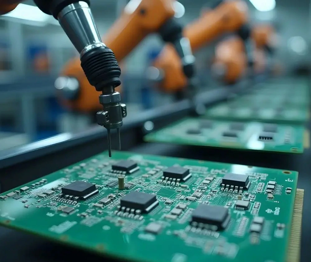
PCB Manufacturing Capability
By harnessing Mars PCB’s modern manufacturing assets, we tightly oversee every production stage to ensure outstanding board performance.
Manufacturing PCB Process
No two PCBs are exactly alike. Each one is precisely configured to fulfill a unique application, creating a multi-step process that varies in complexity. Here is a concise explanation of the essential steps required to make a sophisticated, multilayer circuit board.
When partnering with Mars PCB as your PCB supplier, you are investing in quality that stands the test of time. Our focus on rigorous product requirements and stringent quality checks not only surpasses industry norms but also confirms reliable performance. The outline below provides insight into the distinct aspects that make the Mars PCB workflow go beyond standard practices.
For details on PCB manufacturing procedures, please get in touch with our engineers at Mars PCB. This overview highlights some of our capabilities; if you need a full equipment list or more specifics, feel free to contact us. Below is a sample sequence for a multilayer PCB fabrication:
Mars PCB Process

Engineering Document Production
In PCB manufacturing, Computer-Aided Manufacturing (CAM) is critical for converting circuit outlines into specialized files used during fabrication. Essentially, CAM converts design data into production-ready information that guides imaging steps and drilling processes.
Within this workflow, CAM accomplishes multiple tasks, such as reformatting Gerber files, analyzing the production route, refining the process, preparing operational documentation, and verifying the overall flow. In brief, CAM tools bridge the gap between initial plans and real manufacturing by accurately shifting design input into tangible circuit boards.

Material Cutting
Producing a PCB typically begins with a large copper-clad sheet. Since every factory has strict restrictions on workable dimensions, the initial step is to cut the raw material into appropriate panel sizes. At Mars PCB, we follow a guided Manufacturing Instruction (MI) that specifies how each copper-clad laminate (CCL) should be trimmed to fit subsequent production steps. This level of precision sets the foundation for the entire process.

Print Inner Layers
To define circuit traces on internal layers, we use a photoimageable dry film combined with UV exposure. Bright light cures the dry film in specific spots, ensuring the correct circuit image is formed. This entire process takes place in a clean room to avoid contamination.
During imaging, design files are transformed into a format appropriate for a photoplotter. This device then directs UV light through a film, imprinting a negative image onto the board. The layout that remains after developing is the copper pattern for further processing.

Inner Layer Etching
After the interior pattern is developed, extra copper must be dissolved to reveal the intended circuit layout. This etching step is meticulously managed to maintain the correct thickness and preserve precise features. Once etching is complete, the used dry film is stripped away, exposing the perfected copper traces that match the design.

Inner Layer AOI
Mars PCB conducts an inner-layer Automatic Optical Inspection (AOI) to catch any deviations early on. This system compares the actual circuit patterns to the original data and flags open circuits, shorts, or irregularities. Notably, we do not fix open circuits, reflecting our unwavering approach to total quality. This commitment means each panel upholds a high standard before advancing to the next phase.
Oxidation
Brown oxide, also called black oxide, plays a key role in boosting the bond strength between copper layers and insulating materials. By applying a controlled chemical finish, a thin oxide coating is formed, improving both adhesion and soldering reliability. This step adds a protective barrier to extend PCB shelf life and improve solder results.
Lay-up and Bond (Lamination)
After oxidation, the inner layers are stacked with prepreg insulation and copper foils on top and bottom. Heat and pressure fuse these layers into a unified structure. The lamination process utilizes temperatures of around 375°F and pressures between 275-400 psi. Careful heating and cooling solidify the board into a stable, high-quality PCB ready for further operations.
Drilling the PCB
Drilling is vital to link layers using plated holes, also known as vias, and to accommodate through-hole components. At Mars PCB, we rely on CNC drills and specialized software for exact hole placements. We can provide both round holes and plated slots, useful for specialized needs like RF circuits or high-current paths. Our capabilities ensure accurate alignment and robust connectivity.
Electroless Copper Deposition
Electroless copper deposition coats the newly drilled holes with a subtle copper layer to enable electrical continuity between each layer. Through a chemically moderated process, even non-metallic hole walls gain a uniform copper film. Afterward, additional plating on the entire panel boosts thickness to about 5–8 microns, setting up the board for future steps that require precise track width and spacing.

Outer Dry Film
(Image the Outer Layers)
Before crafting the external circuitry, we apply a photosensitive dry film over the copper. Next, UV light passes through a photomask, hardening specific areas on the dry film. The regions not exposed to UV wash away, uncovering the copper that must be etched. Stripping the dry film at the end reveals the etched traces as dictated by the design.

Graphic Plating
This electroplating stage adds a vital layer of copper onto the outer trace outlines. By controlling current levels and solution chemistry, we build up enough copper thickness to enhance reliability and conductivity. This reinforcement helps the circuit withstand environmental stresses and ensures top-notch electrical function.

Etch Outer Layer
Next, extra copper on the outer surfaces is meticulously removed. This etching step refines the structure of the top and bottom conductors to match design files. By precisely timing chemical baths, we preserve fine details while clearing unwanted copper, solidifying circuit accuracy and uniformity.

Outer Layer AOI
Mars PCB’s outer-layer Automated Optical Inspection scrutinizes each panel to confirm the correct patterns after etching. The AOI’s imaging system cross-references data to find incorrect line widths, bridging, or other potential flaws. By isolating and analyzing any imperfections, we halt defective boards from advancing, ensuring that only superior products move onward.

Solder Mask
Solder mask application prevents solder overflow and shields copper features from contamination or accidental bridging. This layer is carefully coated to exposed areas, with openings where solder joints are intended. The mask’s durability extends a board’s lifespan, enhances environmental protection, and simplifies subsequent assembly.

Legend & Silkscreen
Clear labeling of each PCB is vital for trouble-free assembly and maintenance. By printing component references, outlines, logos, or other details, we enable quick part identification, reduce mistakes, and support consistent product handling. Silkscreen markings reflect the professional finish and facilitate smooth integration into various electronic applications.

Surface Finish
Different surface coatings safeguard exposed copper and ensure dependable solder connections. Widely used choices include ENIG (Electroless Nickel Immersion Gold), HASL (Hot Air Solder Leveling), or Immersion Silver, each applied to a controlled thickness. These protective finishes help prevent oxidation while maintaining the board’s performance.

Electronic Test
Both impedance checks and continuity tests are vital to confirm that each circuit path works as planned. Impedance testing matches expected values in high-speed designs, while functional tests such as flying probe or fixture-based methods verify that there are no shorts or open circuits. These steps guarantee that every PCB meets the intended technical criteria.

Profile
During the profiling phase, multi-unit panels or single boards are cut or scored according to customer drawings. Scoring, routing, or punching can separate the boards. Our team reviews all measurements diligently to confirm the correct dimensions and shape before moving on to final checks.

Final Inspection
Our last step involves thoroughly checking each PCB visually and comparing it with design documents. We use Automated Visual Inspection (AVI) and skilled personnel to validate overall quality. Dimensional integrity and soldering readiness are likewise assessed. At Mars PCB, we devote great care to these final audits to ensure that our boards meet consistent, stringent standards.

Reliability Test
Mars PCB provides specialized reliability checks to meet high performance expectations. Our equipment includes climate chambers, test benches, and electrical analyzers. We strive to deliver enduring, high-quality boards that thrive in demanding situations.
Below are samples of our reliability test gear. To learn more or get a full equipment list, contact us anytime.
Package
Packaging is the concluding step, focusing on safeguarding every board in transit. Special packing materials protect boards from impact, static electricity, and dust. By sizing packaging carefully to match each order’s needs, we help preserve your boards in pristine condition until they are integrated into electronic systems.

Finished Product Warehouse
Finally, completed PCBs are placed in a secure storage area until shipment. This controlled warehouse safeguards products against mechanical harm, static discharges, and harsh conditions. With each item accurately tagged and arranged, it’s ready for seamless delivery to your facility or onward to the next stage of production.
PCB Manufacturing Capability
| Item | Standard | Advanced | Item | Standard | Advanced | |||
| Max Layer Count | Rigid | 64 | 100 | Copper Weight | 1/5oz – 10oz | 1/7oz – 14oz | ||
| Flex | 6 | 10 | Hole(min) | Mechanical | 200um | 150um | ||
| Rigid-Flex | 22 | 26 | Laser | 100um | 100um | |||
| Thickness | Rigid | 0.2mm – 10mm | 0.1mm – 14mm | Vias’ Pad | Mechanical | 350um | 300um | |
| Flex | 0.08mm – 0.8mm | 0.06mm – 1.0mm | Laser | 250um | 200um | |||
| Size | Width | 10.0mm – 800.0mm | 3.0mm – 900.0mm(Multi800) | Hole Aspect Ratio | 1:16 | 1:18 | ||
| Length | 10.0mm – 1500.0mm | 3.0mm – 2100.0mm(Multi1320) | Min Deletric Thickness | Inner Core | 0.025mm | 0.025mm | ||
| Tracks | Width | 70um | 50um | Prepreg | 0.05mm | 0.05mm | ||
| Gap | 70um | 50um | HDI | 4 + N + 4 | 9 + N + 9 | |||
| Via Filling(with) | Soldermask/Resin/plating/copper & silver paste | Solder Mask Bridge | 75um | 60um | ||||
| Embedded Passive | Capacitor | ★ 3M C-Ply, Dupont HK04J,Sammina (BC-2000), Mitsu Faradflex,OKA-Mitsui,Faradflex BC12M, BC24M ★ Dielectric thickness:12um,14um,25um ★ Capacitance/area:0.8nF/in2 – 10nF/in2 ★ No license needed/Customization | Materials | ★Standard FR4,lead free compatible ★High speed, low loss ★Halogen free ★High Frequency ★Advanced microwave materials from Rogers/Arlon/Taconic,etc. ★Special application material such as copper invar copper,customization etc. | ||||
| Resistor | Resistance(ohms/sq):25, 50, 100, 200; Ohmega-Ply, Asahi Tu-50/1000-08 | |||||||
| Materials | Burried Copper/Ceramic/Coin/Steel/other metal/Components | Surface Treatment | Soft gold Hard gold Flash Gold OSP ENIG HAL LF HAL Immersion Tin Immersion Silver ENEPIG | |||||
| Tolerance(+/-) | Hole | 0.075mm | 0.025mm | |||||
| Slot | 0.1mm | 0.05mm | ||||||
| Tracks | 15% | 10% | ||||||
| Outline | 0.1mm | 0.08mm | ||||||
| Impedance | 8% | 5% | ||||||
| Dielectric | 15um | 10um | ||||||
| Depth Control | 150um | 100um | ||||||
Professional PCB & PCB Assembly Manufacturer & Factory
From concept to completion, your project will be under experienced project management, sparing you the hassle of untimely conference calls, communication gaps, language barriers and “real time” information gathering.