PCB Quality Control
12 Methods for Quality Assurance in PCB Manufacturing
Understanding what makes a printed circuit board (PCB) reliable is crucial for ensuring the performance of your devices. At Mars PCB, we specialize in PCB assembly, offering comprehensive quality control to ensure your PCBs meet the highest industry standards. Our services include design assessments and component verification, making sure every part of your PCB is optimized for functionality and durability.
PCB quality control methods are vital for PCB manufacturing and assembly, ensuring the reliability and performance of electronic products.
Mars PCB fully understands the importance of quality control in PCB manufacturing, and we aim to provide peace of mind as your trusted PCB partner. This article explores various testing and inspection methods used in our PCB quality control processes.
Key Takeaways
- PCB quality control includes multiple inspection and testing methods to ensure precision, reliability, and efficiency.
- Visual and automated inspections like AOI and X-rays are essential for detecting visible and hidden defects.
- Electrical testing methods such as ICT and functional testing confirm component functionality and overall PCB performance.
- Environmental and stress testing techniques ensure PCBs can withstand real-world operating conditions.
- Specialized inspections like cleanliness testing and thermal imaging address specific quality concerns in PCB manufacturing.

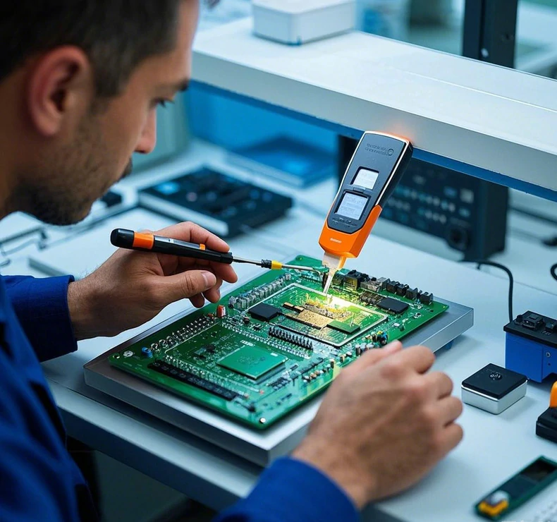
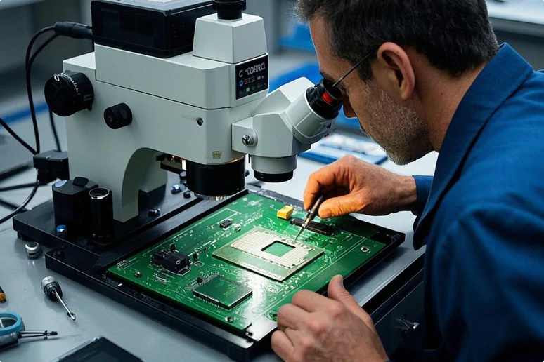
Visual Inspection
Visual inspection is typically the first step in PCB quality assurance. The primary goal of this PCB quality control system is to identify visible defects.
This inspection method involves trained professionals carefully examining PCBs for defects such as misaligned components, solder bridges, or damaged traces. Visual PCB inspection can detect issues like:
- Incorrect component placement
- Solder mask defects
- Scratches or physical damage to the PCB
- Missing or incorrect components
- Poor solder joint quality
While visual inspection is important, it has limitations in detecting hidden defects or issues within PCB layers. Therefore, it is used alongside other inspection methods to ensure comprehensive quality control in PCB manufacturing.

Automated Optical Inspection
Automated Optical Inspection (AOI) is a crucial step in PCB quality control manufacturing processes. It utilizes high-resolution cameras and advanced image processing algorithms to identify defects.
AOI systems can inspect PCBs much faster and more accurately than manual inspections, making them highly effective in high-volume PCB manufacturing. Key features of AOI in PCB quality control include:
- Inspection of solder joints, component placement, and polarity
- Detection of missing or incorrect components
- Identification of solder bridges and insufficient solder
- Verification of correct component values and markings
AOI systems can be customized to meet specific PCB manufacturer quality standards and customer requirements, ensuring each PCB meets intended specifications. This automated process enhances the overall quality and reliability of PCB products while reducing the time and cost associated with manual inspection.

X-ray Inspection
X-ray inspection is a non-destructive testing method used to examine hidden solder joints and internal defects within PCB designs. This technique is beneficial for inspecting multilayer PCBs, ball grid arrays (BGAs), and other components with concealed connections.
Advantages of X-ray inspection in PCB quality control include
- Detection of voids in solder joints
- Identification of internal short circuits or open circuits
- Inspection of through-hole component soldering
- Verification of proper alignment in multilayer PCBs
Incorporating X-ray inspection into a quality management system allows PCB manufacturers to ensure the quality of connections that are not visible to the naked eye or traditional optical inspection methods. This improves the final product’s reliability and reduces the risk of field failures.

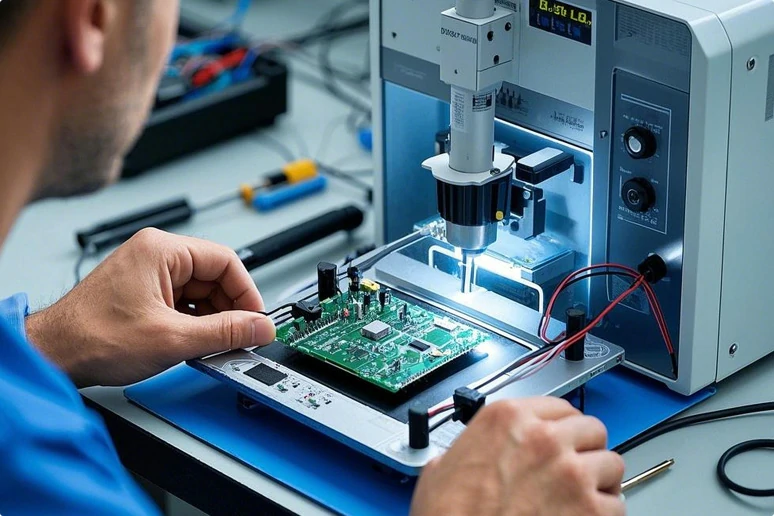
In-Circuit Testing
In-Circuit Testing (ICT) is a comprehensive method used to verify the functionality of individual components on a PCB. This testing technique employs a bed-of-nails fixture to contact specific test points on the PCB, enabling fast and accurate testing of various electrical parameters. Key features of ICT include:
- Testing of component values (resistance, capacitance, inductance)
- Verification of proper component orientation and polarity
- Detection of short circuits and open circuits
- Functional testing of active components (e.g., diodes, transistors)
ICT effectively identifies manufacturing defects and ensures that each component on the PCB meets its specified electrical characteristics and maintains high quality.
Flying Probe Testing
Flying Probe Testing (FPT) is a flexible and cost-effective method for testing PCBs, suitable for low-volume production or prototype boards. Unlike ICT, which requires a custom fixture for each PCB design, FPT uses movable probes to contact test points on the board.
Benefits of FPT as part of strict quality control methods include:
- No need for expensive custom fixtures
- Easily adaptable to different PCB designs
- Ability to test hard-to-reach areas on densely populated boards
- Quick setup time for new PCB designs
Flying Probe Testing can perform many of the same electrical tests as ICT, including continuity checks, short circuit detection, and component value verification. This method ensures high-quality, reliable PCBs where the cost of a custom ICT fixture may not be justified.
Functional Testing
Functional testing is a crucial aspect of the quality assurance process that verifies the overall performance of the assembled circuit board. This testing method simulates the PCB’s actual operating conditions to ensure it functions as intended.
Key areas of functional testing in PCB assembly include:
- Verification of proper input/output responses
- Testing of various operating modes and functions
- Performance testing under different load conditions
- Compatibility testing with other system components
Functional testing helps identify issues that may not be apparent through other testing methods, such as timing problems, signal integrity issues, or software-related defects. By ensuring that the PCB performs its intended functions correctly, this testing method is vital for maintaining high-quality standards and customer satisfaction.

Burn-in Testing
Burn-in testing is a robust quality control method used to identify potential early-life failures in PCBs. This process involves operating the PCB under elevated stress conditions, typically high temperature and high voltage, for an extended period. Key features of burn-in testing in quality assurance include:
- Accelerated aging of components to reveal latent defects
- Identification of weak components that may fail prematurely
- Verification of long-term reliability and performance
- Reduction of infant mortality rates in electronic products
Exposing PCBs to these stress conditions allows manufacturers to identify and eliminate boards with marginal components or manufacturing defects before they reach the end user. This process significantly enhances the overall reliability and lifespan of the final product as part of your PCB manufacturing service.

Environmental Stress Screening
Environmental Stress Screening (ESS) is a quality control method used to assess how durable PCBs are under various environmental conditions. This testing process exposes PCBs to a range of stressors that mimic real-world operating environments.
ESS typically includes:
- Temperature cycling tests
- Humidity exposure tests
- Vibration testing
- Shock testing
- Altitude simulation
Subjecting PCBs to these environmental stresses enables manufacturers to identify potential weaknesses or defects that may not be evident under normal conditions. ESS ensures that PCBs will perform consistently in their intended operating environments, whether in automotive, aerospace, or other demanding applications.

Electrical Safety Testing
Electrical safety testing is crucial for products used in consumer or industrial applications. This testing ensures that the PCB and the final product comply with relevant safety standards and regulations.
Key components of electrical safety testing include:
- Hipot (dielectric withstand) testing
- Insulation resistance testing
- Ground continuity testing
- Leakage current testing
These tests ensure that the PCB can handle specified voltage levels without breakdown and provides adequate protection against electric shock. Compliance with safety standards such as UL, CE, or IEC is essential for product certification and customer safety.

Cleanliness Testing
Cleanliness testing ensures that boards are free from contaminants that could affect their performance or reliability. This testing is particularly important for PCBs used in high-reliability applications or harsh environments.
Common cleanliness testing methods include:
- Ionic contamination testing
- Surface insulation resistance (SIR) testing
- Visual inspection under UV light
- Solvent extract conductivity testing
These tests help identify residues from the manufacturing process, such as flux residues or cleaning agent remnants, which could lead to corrosion, short circuits, or other reliability issues over time.
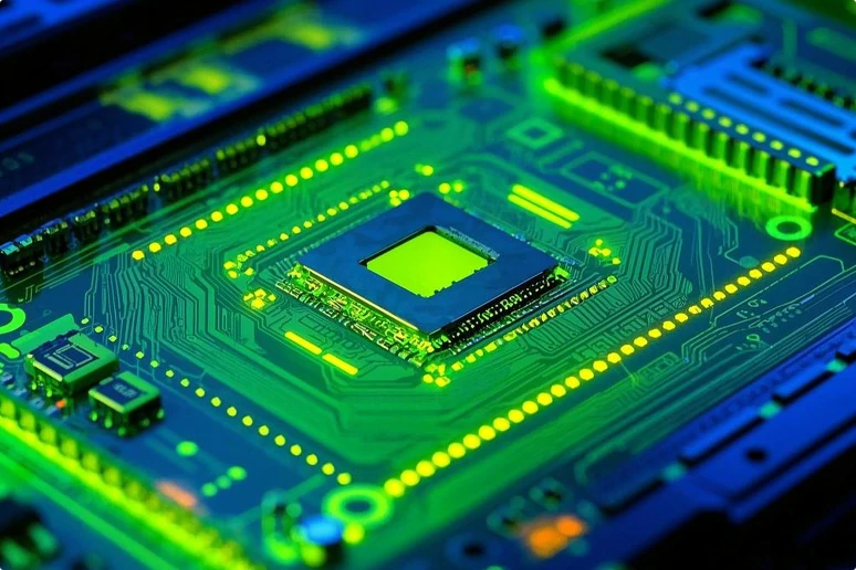
Thermal Imaging
Thermal imaging is a non-contact inspection method used to detect heat-related issues. This technique uses infrared cameras to capture the heat signature of a powered PCB, allowing inspectors to identify problems like:
- Overheating components
- Poor heat dissipation
- Uneven heat distribution
- Short circuits causing localized heating
Detecting these thermal anomalies helps manufacturers address reliability issues before they result in product failures. Thermal imaging is particularly useful for high-power PCBs or designs with stringent thermal management requirements.
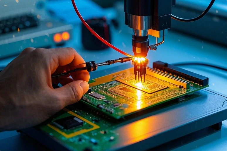
Solder Paste Inspection
Solder Paste Inspection (SPI) is conducted before component placement in the PCB assembly process. This automated inspection method uses advanced optical systems to verify the quality and quantity of solder paste deposited on PCB pads and checks for solderability.
Key aspects of SPI include:
- Verification of solder paste volume and height
- Detection of bridging between pads
- Identification of missing or insufficient solder paste
- Measurement of pad coverage and alignment
SPI helps prevent defects such as solder bridges, insufficient connections, or component misalignment. This proactive quality control measure enhances the overall quality of the soldering process and reduces the likelihood of defects in the final assembled PCB.
Mars PCB: High-Quality PCB Assembly
At Mars PCB, we recognize the importance of comprehensive quality control in PCB assembly services. Our advanced facilities utilize these testing and inspection methods to ensure that every PCB we produce meets the highest quality standards.
Choose Mars PCB for your next project and experience the difference that true quality assurance can make. Contact us to bring your PCB vision to life and learn how we can help you achieve the reliability and performance you need.
PCB Quality Control:
12 Methods for Quality Assurance in PCB Manufacturing FAQs
PCB manufacturing standards are industry-wide guidelines that define quality, performance, and safety requirements for printed circuit boards. These standards, such as IPC and ANSI, ensure consistency and reliability across PCB assembly and manufacturing processes.
Restriction of Hazardous Substances (RoHS) is a European Union directive that limits the use of certain hazardous materials in electrical and electronic equipment. It aims to reduce environmental impact and health risks by restricting substances like lead, mercury, and cadmium in PCBs and other electronic products.
Controlling PCB raw materials involves strict supplier selection and incoming material inspection processes. This includes verifying material specifications, conducting chemical analyses, and performing physical tests. This ensures the quality and consistency of base materials, copper foils, and other components used in PCB manufacturing.
Your One-Stop PCB Assembly Factory
From concept to completion, your project will be under experienced project management, sparing you the hassle of untimely conference calls, communication gaps, language barriers and “real time” information gathering.