A Rigid-Flex PCB is a hybrid circuit board that strategically combines elements from both hardboard (rigid) and flexible circuits into a single, integrated unit. This innovative structure features rigid sections for mounting components, interconnected by flexible sections that can be bent, twisted, and folded to fit into compact or unusually shaped devices. The primary goal of a rigid-flex design is to provide a robust, reliable, and three-dimensional interconnection solution that eliminates the need for traditional connectors, cables, and wires, thereby reducing weight, size, and potential points of failure.
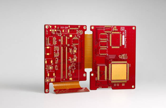
Table of Contents
- What is a Rigid-Flex PCB?
- Why Choose a Rigid-Flex PCB? The Core Advantages
- Deconstructing the Rigid-Flex PCB Structure: A Layer-by-Layer Breakdown
- Exploring Rigid-Flex PCB Materials: The Building Blocks of Hybrid Circuits
- Understanding the Rigid-Flex PCB Stack-Up: The Blueprint for Performance
- The Manufacturing Process: How Are Rigid-Flex PCBs Made?
- Design Considerations for Optimal Reliability
- Common Applications of Rigid-Flex PCBs
- Conclusion: The Future of Interconnection is Hybrid
- Frequently Asked Questions (FAQ)
What is a Rigid-Flex PCB?
At its core, a Rigid-Flex Printed Circuit Board represents the pinnacle of electronic packaging, merging the durability of rigid FR-4 boards with the adaptability of flexible circuits. Unlike conventional assemblies that require separate PCBs connected by wires and connectors, a rigid-flex board integrates these elements into a unified whole. The rigid areas provide stable platforms for mounting sensitive and high-pin-count components like microprocessors and connectors, while the flexible “ribbons” or “spines” house conductive traces that maintain electrical connection as the board is bent into its final shape. This hybrid approach delivers a streamlined, reliable, and space-efficient solution for complex electronic designs.
Why Choose a Rigid-Flex PCB? The Core Advantages
The decision to use a rigid-flex PCB is driven by a unique set of benefits that traditional boards cannot offer. These advantages are crucial for modern electronics, especially in industries where space, weight, and reliability are paramount.
- Space and Weight Reduction: By eliminating bulky connectors and cables, rigid-flex designs significantly reduce the overall footprint and weight of an electronic assembly. This is a game-changer for portable devices, aerospace technology, and medical implants.
- Enhanced Reliability: The seamless transition between rigid and flex sections minimizes potential points of failure. Solder joints for connectors are a common source of mechanical and electrical faults; rigid-flex PCBs eliminate many of these, leading to a more robust final product with improved signal integrity.
- Dynamic Flexing and 3D Design Freedom: Rigid-flex circuits enable designers to think in three dimensions. The board can be folded and contorted to fit into complex enclosures, maximizing the use of available space and allowing for more innovative product forms.
- Simplified Assembly: Although the board itself is more complex to fabricate, it simplifies the final product assembly process. Instead of connecting multiple boards with delicate ribbon cables, a single rigid-flex unit can be installed, reducing assembly time, labor costs, and the risk of human error.
- Improved Shock and Vibration Resistance: The inherent flexibility of the polyimide sections allows the board to absorb and dampen vibrations more effectively than a stiff, rigid board. This makes rigid-flex a superior choice for applications in harsh environments, such as automotive and industrial machinery.
Deconstructing the Rigid-Flex PCB Structure: A Layer-by-Layer Breakdown
To truly understand a rigid-flex PCB, one must visualize it as a composite structure where different materials and layers serve distinct purposes. The entire construction is laminated together under heat and pressure to form a cohesive, functional unit.
The Rigid Sections: Stability and Component Mounting
The rigid portions of the board are functionally identical to a standard PCB. They are built from multiple layers of materials like FR-4 or high-temperature laminates. These sections provide the mechanical support necessary for mounting SMT (Surface Mount Technology) and through-hole components. They contain power and ground planes, high-density routing, and are robust enough to withstand the stresses of assembly and everyday use. The thickness and layer count of the rigid sections can be customized to meet specific electrical and mechanical requirements, such as impedance control or structural integrity.
The Flexible Sections: Dynamic Bending and Interconnection
The flexible heart of the board is what sets it apart. These sections are built around a thin, pliable base material, most commonly Polyimide (PI). Copper traces are etched onto this flexible core to form the circuit pathways that connect the different rigid parts. The key characteristic here is the ability to bend without compromising electrical continuity. The design of the flex area is critical; traces must be routed to minimize stress during bending, often using curved paths instead of sharp 90-degree angles. The number of layers in the flex section is typically kept to a minimum to maximize flexibility and reliability.
The Transition Zone: Where Rigid Meets Flex
Perhaps the most critical area in a rigid-flex design is the transition zone, where the flexible substrate extends into the rigid board. This interface is a point of high mechanical stress and requires careful design to prevent delamination or trace cracking. Manufacturers employ specific techniques, such as creating smooth transitions, anchoring pads (or “coupons”), and using specialized adhesives, to ensure a durable and reliable bond. The integrity of this zone is fundamental to the long-term performance of the entire board.
Exploring Rigid-Flex PCB Materials: The Building Blocks of Hybrid Circuits
The performance, reliability, and cost of a rigid-flex PCB are directly tied to the materials used in its construction. Each material is chosen for its specific properties and role within the stack-up.
Core Materials for the Rigid Sections
The standard choice for rigid sections is FR-4 (Flame Retardant 4), a glass-reinforced epoxy laminate. It offers an excellent balance of cost, manufacturability, and electrical performance. For applications involving higher operating temperatures or lead-free soldering processes, High-Tg FR-4 (with a higher glass transition temperature) is used to prevent the board from deforming.
Core Materials for the Flexible Sections
Polyimide (PI) is the undisputed industry standard for flexible substrates. Its exceptional properties include high thermal stability, excellent dielectric strength, and outstanding mechanical flexibility. It can withstand the high temperatures of soldering and maintain its properties over millions of flex cycles, making it ideal for both static and dynamic applications.
Conductor Materials: RA vs. ED Copper
The conductive traces are made of copper, but not all copper is created equal. Two main types are used:
- Rolled Annealed (RA) Copper: This copper is manufactured by rolling a block of copper into a thin foil. This process creates an elongated grain structure that makes it highly flexible and resistant to fatigue from repeated bending. RA copper is the preferred choice for dynamic flex applications.
- Electro-Deposited (ED) Copper: ED copper is formed by depositing copper ions onto a drum in an electrolytic solution. It has a vertical grain structure, making it less flexible than RA copper but perfectly suitable for static rigid-flex applications where the board is bent only for installation.
Adhesive Systems
Adhesives are used to bond the copper layers to the polyimide core. The choice of adhesive impacts flexibility and thermal performance.
- Acrylic and Epoxy Adhesives: These are traditional choices, offering strong bonding. However, they can be less flexible and may have lower thermal performance compared to newer options.
- Adhesiveless Laminates: Modern rigid-flex boards often use adhesiveless base materials, where the copper is deposited directly onto the polyimide. This removes the adhesive layer, resulting in a thinner, more flexible, and more thermally stable construction. This is the premium choice for high-performance applications.
Protective Layers: Coverlay vs. Solder Mask
Exposed copper traces need protection from environmental factors and electrical shorts.
- Coverlay: This is the equivalent of solder mask for flexible sections. It is a sheet of polyimide with an adhesive backing that is laminated over the flex circuitry. It is flexible and durable enough to move with the circuit.
- Solder Mask: A liquid photoimageable (LPI) solder mask is applied to the rigid sections to protect traces and define solder pads. It is not flexible and would crack if applied to the flex regions.
Stiffeners
In some cases, specific areas of a flex circuit may need extra support without being fully rigid. Stiffeners, made from materials like FR-4, polyimide, or stainless steel, can be selectively bonded to the board to provide mechanical support for connectors or components, or to increase thickness for ZIF (Zero Insertion Force) connector requirements.
| Component | Material Option 1 | Material Option 2 | Primary Use Case |
|---|---|---|---|
| Rigid Core | Standard FR-4 | High-Tg FR-4 | Standard vs. High-temperature applications |
| Flex Core | Polyimide (PI) | N/A (Industry Standard) | Provides flexibility and thermal stability |
| Conductor | Rolled Annealed (RA) Copper | Electro-Deposited (ED) Copper | Dynamic flexing vs. Static (flex-to-install) |
| Bonding | Adhesive-based | Adhesiveless | Cost-effective vs. High-performance/thinner profile |
| Protection | Coverlay (Flex areas) | Solder Mask (Rigid areas) | Flexible protection vs. Rigid protection |
Understanding the Rigid-Flex PCB Stack-Up: The Blueprint for Performance
The rigid-flex PCB stack-up is the detailed arrangement of all the copper and dielectric layers that make up the board. It is a critical design document that defines the board’s electrical properties, mechanical characteristics, and overall manufacturability.
What is a Rigid-Flex Stack-Up?
A stack-up is essentially a cross-sectional map of the PCB. It specifies the material type, thickness, and sequence of every layer, from the top to the bottom. For rigid-flex boards, the stack-up is more complex because it must define the layers for both the rigid and flexible sections and show how they integrate. A well-designed stack-up ensures controlled impedance for high-speed signals, proper power distribution, and mechanical robustness.
Common Types of Rigid-Flex Stack-Ups
Rigid-flex stack-ups are often categorized based on their complexity and layer count, as defined by industry standards like IPC-2223C.
- Type 1: Single-Sided Flex: The simplest form, featuring a single conductive layer in the flexible section, with rigid sections laminated to one or both sides. This is suitable for basic interconnection needs.
- Type 2: Double-Sided Flex: Features two conductive layers in the flexible section, often with plated through-holes (PTH) connecting them. This allows for more complex routing within the flex area.
- Type 3: Multilayer Flex: This is the most common type for complex products. It involves three or more conductive layers in the flexible section, allowing for high-density routing, shielding, and controlled impedance. The rigid sections can have many more layers.
- Type 4: Complex Multilayer Rigid: This advanced construction involves laminating multiple rigid and flex sections together, creating a highly integrated and dense assembly. It is less common and reserved for specialized applications.
Key Considerations for Designing a Stack-Up
Creating an effective rigid-flex stack-up requires balancing electrical, mechanical, and manufacturing constraints.
- Symmetry: A balanced, symmetrical stack-up is crucial to prevent warping during the lamination process. This means arranging layers symmetrically around the center of the board.
- Layer Count in Flex Area: Keep the number of layers in the flex region to the absolute minimum necessary. Fewer layers mean greater flexibility and a smaller bend radius.
- Material Consistency: Use materials from the same family or manufacturer to ensure compatibility and predictable performance during lamination.
- Controlled Impedance: For high-speed signals, the thickness of the dielectric materials and the width of the copper traces must be precisely controlled to achieve the target impedance (e.g., 50 ohms). This must be defined in the stack-up.
The Manufacturing Process: How Are Rigid-Flex PCBs Made?
Fabricating a rigid-flex PCB is a hybrid process that combines the techniques of both rigid and flexible circuit manufacturing. The flexible layers are processed first, including drilling, plating, and etching. Separately, the rigid layers are processed. Finally, all the layers are carefully aligned and laminated together in a high-temperature, high-pressure press. Subsequent steps like drilling, plating, and finishing are similar to standard PCB manufacturing, but require specialized handling to accommodate the mixed materials.
Design Considerations for Optimal Reliability
Designing a reliable rigid-flex board goes beyond the stack-up. Engineers must consider:
- Bend Radius: The minimum radius to which the flex section can be bent without damage. A general rule is a minimum bend radius of 10x the flex thickness for multilayer flex.
- Trace Routing: Avoid sharp corners. Use curved or arced traces in bend areas to distribute stress evenly.
- Pads and Vias: Vias should be kept out of bend areas. Use tear-dropping or anchoring spurs to reinforce the connection between pads and traces in the transition zone.
- Component Placement: Keep heavy components away from the transition zone to minimize mechanical stress on the interface.
Common Applications of Rigid-Flex PCBs
The unique advantages of rigid-flex technology make it the ideal choice for a wide range of advanced products:
- Aerospace and Defense: Used in avionics, guidance systems, and unmanned aerial vehicles (UAVs) where weight, space, and reliability are critical.
- Medical Devices: Found in pacemakers, defibrillators, and diagnostic imaging equipment where high reliability and compact size are essential.
- Consumer Electronics: Used in smartphones, laptops, digital cameras, and wearable technology to maximize internal space and connect various components.
- Automotive: Deployed in engine control units (ECUs), sensor systems, and GPS modules to withstand vibration and fit into tight spaces.
Conclusion: The Future of Interconnection is Hybrid
The structure of a rigid-flex PCB is a masterful integration of diverse materials and layers, each selected to perform a specific function. By understanding the interplay between the rigid sections for component mounting, the flexible polyimide for dynamic interconnection, and the critical transition zones, engineers can unlock unprecedented design freedom. From the choice of copper and adhesives to the meticulous planning of the stack-up, every detail contributes to a final product that is smaller, lighter, and more reliable than its traditional counterparts. As electronics continue to shrink and become more complex, rigid-flex technology stands out as a foundational solution for the next generation of innovation.
Frequently Asked Questions (FAQ)
1. What is the main difference between a rigid-flex and a flexible PCB?
A flexible PCB is entirely flexible, while a rigid-flex PCB is a hybrid board with both rigid sections (for mounting components) and flexible sections for interconnection. Rigid-flex offers the best of both worlds by providing stable mounting surfaces and integrated flexible connections.
2. Are rigid-flex PCBs more expensive than traditional PCBs?
Yes, the initial fabrication cost of a rigid-flex PCB is higher due to more complex materials and manufacturing processes. However, this cost can be offset by a lower total system cost, as it eliminates the need for connectors, cables, and the labor required to assemble them, while also improving reliability.
3. What is a “bookbinder” rigid-flex design?
A bookbinder construction is used for rigid-flex boards with a high layer count in the flexible section. The flexible layers are designed with progressively longer lengths from the inside of the bend to the outside, allowing them to bend without putting excessive stress on the copper traces, much like the pages of a book.

