Choosing between Rigid, Flex, and Rigid-Flex PCBs involves balancing cost, application demands, and physical constraints. Rigid PCBs are the cost-effective standard for static applications like motherboards. Flex PCBs offer dynamic bending and space-saving for devices like wearables. Rigid-Flex PCBs combine the best of both, providing robust, 3D interconnect solutions for high-reliability applications like aerospace and medical devices, albeit at a higher cost. This guide will delve into the construction, advantages, disadvantages, and ideal use cases for each type, empowering you to select the perfect PCB for your next project.
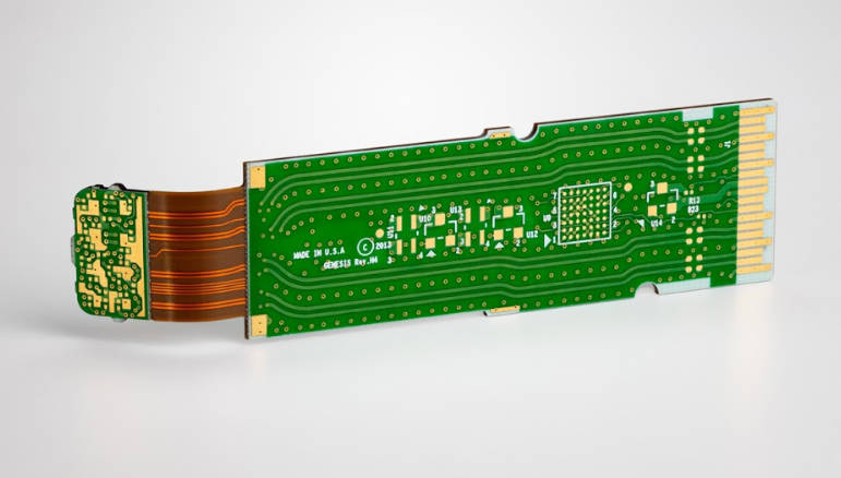
Table of Contents
- What are Printed Circuit Boards (PCBs)? A Quick Refresher
- Decoding the Contestants: Rigid vs. Flex vs. Rigid-Flex
- A Head-to-Head Comparison: Key Differences at a Glance
- Real-World Applications: Where Does Each PCB Type Shine?
- How to Choose the Right PCB for Your Project? Key Factors to Consider
- Conclusion: Making the Final Decision with Confidence
- Frequently Asked Questions (FAQ)
What are Printed Circuit Boards (PCBs)? A Quick Refresher
Before diving into the comparisons, let’s establish a baseline. A Printed Circuit Board (PCB) is the foundational building block of nearly all modern electronics. It’s a board or substrate that mechanically supports and electrically connects electronic components using conductive tracks, pads, and other features etched from one or more sheet layers of copper laminated onto a non-conductive substrate. Essentially, it’s the neat, organized, and reliable replacement for the old, messy point-to-point wiring systems. The type of substrate material used is what primarily differentiates the boards we are discussing today.
Decoding the Contestants: Rigid vs. Flex vs. Rigid-Flex
The choice of PCB is one of the most critical decisions in electronic product design. It dictates the product’s form factor, durability, and cost. Let’s break down the three primary contenders.
What is a Rigid PCB? The Unyielding Workhorse
As the name implies, a Rigid PCB is a circuit board that cannot be bent or twisted. It is the most common and widely recognized type of PCB. The foundation of a rigid board is a solid substrate material that gives it its rigidity and strength, preventing it from deforming.
Construction and Materials: The primary substrate material for rigid PCBs is FR-4 (Flame Retardant 4), a glass-reinforced epoxy laminate. It’s a composite material composed of woven fiberglass cloth with an epoxy resin binder that is flame resistant. This material provides excellent mechanical strength, dimensional stability, and favorable electrical properties, all at a very low cost. Other materials like metal-core PCBs (for heat dissipation) or ceramics (for high-frequency applications) also exist but FR-4 is the industry standard.
- Pros:
- Low Cost: Established manufacturing processes and inexpensive materials make rigid PCBs the most affordable option, especially for high-volume production.
- High Durability: Their strength and rigidity make them highly resistant to stress and environmental factors.
- Simplicity in Design & Manufacturing: The design rules and assembly processes are standardized and well-understood, leading to faster turnaround times and fewer manufacturing defects.
- Excellent Reliability: Strong, well-defined solder joints and component mounts contribute to a long and reliable service life.
- Cons:
- Inflexibility: They cannot be bent or shaped to fit into unconventional or tight spaces.
- Larger Size and Weight: The rigid substrate and need for connectors to link multiple boards can lead to bulkier and heavier final products.
- Limited to 2D Designs: The design is confined to the X and Y planes, which can be a limitation for highly compact devices.
What is a Flex PCB? The Adaptable Innovator
A Flex PCB, also known as a flexible circuit or FPC (Flexible Printed Circuit), is a circuit board built on a pliable, flexible substrate. These circuits can be bent, twisted, and folded to fit into complex, three-dimensional spaces, a feat impossible for their rigid counterparts.
Construction and Materials: The most common substrate for flex circuits is Polyimide (PI), a high-performance polymer known for its excellent thermal stability, chemical resistance, and flexibility. Thin sheets of copper are laminated onto the polyimide film to create the conductive traces. Because they are designed to bend, the entire material stack-up, including adhesives and coverlays, is optimized for flexibility.
- Pros:
- Space and Weight Savings: Their ability to fold and bend allows for significant miniaturization and weight reduction in electronic devices.
- Improved Reliability: By replacing bulky connectors, wires, and ribbon cables with integrated flexible circuits, the number of potential failure points (like solder joints) is drastically reduced.
- Dynamic Flexing: Flex circuits can be designed for applications that require constant movement, such as in printer heads or robotic arms.
- Enhanced Durability: They have superior resistance to vibrations and shocks compared to rigid boards with connectors.
- Cons:
- Higher Cost: The materials (polyimide) and more complex manufacturing processes make flex circuits more expensive than rigid PCBs.
- Complex Handling: Their flimsy nature can make them challenging to handle during assembly, often requiring special fixtures or carriers.
- Lower Durability to Abrasion: While excellent at flexing, they can be more susceptible to damage from scratching or improper handling than a robust FR-4 board.
What is a Rigid-Flex PCB? The Best of Both Worlds
A Rigid-Flex PCB is a hybrid board that combines the technologies of both rigid and flexible circuits. It consists of rigid circuit sections that are interconnected by integrated flexible circuit sections. This construction allows for the mounting of components on the rigid areas while leveraging the flexible parts for connection and 3D form factors.
Construction and Materials: A rigid-flex board is manufactured by selectively laminating rigid FR-4 layers with flexible polyimide layers into a single, cohesive unit. This is a highly complex process that requires precise alignment and specialized lamination techniques. The result is a unified board with no connectors between the rigid and flex sections, creating a highly reliable electromechanical structure.
- Pros:
- Ultimate 3D Design Freedom: They provide the most streamlined solution for complex, three-dimensional product designs, eliminating the need for most cables and connectors.
- Highest Reliability: The elimination of connectors and solder joints between boards creates the most robust and reliable interconnect solution, ideal for high-vibration and high-shock environments.
- Optimal Space & Weight Reduction: They offer the density of a rigid PCB with the form-factor advantages of a flex circuit, achieving the highest possible degree of miniaturization.
- Simplified Assembly: Although the board itself is complex to build, it can simplify the final product assembly by reducing the number of parts and connection steps.
- Cons:
- Highest Cost: The combination of materials and extremely complex, low-yield manufacturing processes makes rigid-flex the most expensive PCB option by a significant margin.
- Complex Design & Manufacturing: Designing a rigid-flex board is a highly specialized skill, and manufacturing requires advanced capabilities and stringent process controls.
A Head-to-Head Comparison: Key Differences at a Glance
To help you visualize the trade-offs, here is a direct comparison of the three PCB types across several critical parameters.
| Feature | Rigid PCB | Flex PCB | Rigid-Flex PCB |
|---|---|---|---|
| Cost | Lowest | Medium | Highest |
| Flexibility | None | High (Static and Dynamic) | Selective (Flex sections only) |
| Durability | High (to impact/abrasion) | High (to vibration/shock) | Highest Overall |
| Size & Weight | Largest / Heaviest | Smallest / Lightest | Very Small / Light |
| Design Complexity | Low | Medium | High |
| Connector Requirement | High (for board-to-board) | Low (can replace cables) | Lowest (integrated connections) |
Real-World Applications: Where Does Each PCB Type Shine?
The theoretical pros and cons come to life when we examine where these boards are used in the real world. The application often dictates the board type.
Common Applications for Rigid PCBs
Due to their low cost and durability, rigid PCBs are ubiquitous. You’ll find them in almost any device that doesn’t require movement or extreme space constraints.
- Consumer Electronics: Desktop computers (motherboards, graphics cards), televisions, game consoles, and home appliances.
- Power Electronics: Power supplies, inverters, and battery management systems where robust component mounting and heat dissipation are key.
- Industrial Controls: Automation controllers, robotics control units, and measurement equipment that reside in stable, protected enclosures.
- IoT Devices: Many stationary IoT sensors and hubs where cost is a primary driver and the form factor is not highly constrained.
When to Use Flexible PCBs?
Flexible PCBs are the solution when a circuit needs to fit into a tight, irregularly shaped space or endure movement.
- Wearable Technology: Smartwatches, fitness trackers, and smart clothing where the circuit must conform to the human body.
- Medical Devices: Hearing aids, pacemakers, and flexible medical sensors that require biocompatibility and compact design.
- Automotive: In-dash displays, airbag systems, and sensor connections in tight spaces like door hinges.
- Cameras & Mobile Phones: Connecting camera sensors, displays, and keypads within the device’s slim profile.
Prime Use Cases for Rigid-Flex PCBs
Rigid-flex boards are reserved for high-performance applications where reliability is non-negotiable and cost is a secondary concern.
- Aerospace & Defense: Avionics, missile guidance systems, and satellite electronics that must withstand extreme vibration and shock while being incredibly lightweight.
- Advanced Medical Equipment: High-end imaging scanners (MRI, CT), surgical tools, and implantable devices where absolute reliability is a matter of life and death.
- High-End Drones: Connecting sensors, cameras, and flight controllers in a compact, vibration-resistant package.
- Automotive (Advanced): Critical sensor systems for autonomous driving and complex lighting assemblies where space is limited and reliability is paramount.
How to Choose the Right PCB for Your Project? Key Factors to Consider
Making the right choice comes down to a careful evaluation of your project’s specific needs. Ask yourself these critical questions.
Evaluating Your Budget: Cost vs. Performance
This is often the first and most important consideration. Rigid PCBs are always the cheapest option. If your design can be implemented on a flat, static board and fits within your product’s enclosure, a rigid PCB is the default choice. A Flex circuit will increase costs, and a Rigid-Flex design will increase them substantially. You must justify the added expense with a clear need for flexibility, space savings, or enhanced reliability that a rigid board cannot provide.
Analyzing Space and Form Factor Constraints
How much space do you have? Is the shape of the enclosure unconventional? If your product is extremely compact or has a unique shape (like a wearable device), a Flex or Rigid-Flex PCB is likely necessary. They allow you to fold the electronics to fit the mechanical design, rather than designing the enclosure around a flat board. This is a primary driver for moving away from rigid solutions.
Assessing Reliability and Environmental Demands
Will the device experience vibration, shock, or repeated movement? Connectors are a common point of failure. If your device will be subject to harsh conditions, the integrated connections of a Rigid-Flex PCB offer unparalleled reliability. For applications with dynamic flexing, like a laptop hinge or printer carriage, a dedicated Flex PCB is specifically designed to withstand millions of bend cycles.
Conclusion: Making the Final Decision with Confidence
The debate of Rigid vs. Flex vs. Rigid-Flex PCBs is not about finding a single “best” option, but about identifying the *right* solution for a specific problem. Each type represents a different point on the spectrum of cost, flexibility, and complexity.
- Go with a Rigid PCB for cost-driven, standard applications where space and form factor are not major constraints. They are the reliable, affordable workhorses of the electronics industry.
- Choose a Flex PCB when your design needs to bend, fold, or fit into a tight, irregular space, and you need to eliminate connectors for a lighter, more compact product.
- Invest in a Rigid-Flex PCB for mission-critical applications where the highest level of reliability, combined with 3D design freedom, is required, and the high cost can be justified.
By carefully weighing your project’s mechanical requirements, environmental conditions, and budget, you can confidently select the PCB technology that will best serve your product and ensure its success.
Frequently Asked Questions (FAQ)
Q1: Are rigid-flex PCBs more reliable than rigid PCBs with connectors?
A: Yes, significantly. By eliminating the solder joints, crimps, and physical contact points of connectors and cables, rigid-flex PCBs remove the most common sources of intermittent faults and mechanical failure in high-vibration and high-shock environments.
Q2: Can you place components on the flexible parts of a PCB?
A: It is generally not recommended to mount components on the flexible sections of a flex or rigid-flex PCB, especially if that area is intended to bend. The stress of flexing can damage the solder joints and the components themselves. Stiffeners are often added to flex areas if component mounting is absolutely necessary and the area will not be subject to dynamic bending.
Q3: What is the main material difference between rigid and flex boards?
A: The main difference is the substrate. Rigid boards primarily use FR-4, a glass-epoxy composite, which is hard and unbendable. Flex boards use Polyimide (PI), a durable and flexible polymer that can withstand high temperatures and repeated bending.
Q4: How much more expensive are flex and rigid-flex PCBs?
A: The cost can vary widely based on complexity, layer count, and volume. As a rough estimate, a flex PCB can be 3-5 times more expensive than a comparable rigid PCB. A rigid-flex PCB can be 5-20 times more expensive, or even more for highly complex aerospace-grade designs.
Anchor Text Suggestions
- Internal Linking: “our PCB design services”, “understanding PCB materials”, “guide to PCB assembly”, “FR-4 substrate properties”
- External Linking (Authoritative Sources): “IPC standards for flexible circuits”, “Altium’s guide to rigid-flex design”, “research on polyimide materials”
Rigid vs Flex vs Rigid-Flex PCB, rigid pcb, flex pcb, rigid-flex pcb, printed circuit board comparison, what is a rigid pcb, advantages of flex pcb, rigid-flex pcb applications, when to use flex pcb, pcb material, FR-4 vs polyimide, flexible circuit design

