What is the difference between a single layer and a double layer aluminum PCB?
The primary difference between a single layer and a double layer aluminum PCB lies in their copper circuitry layers, routing capabilities, and manufacturing complexity. A single layer aluminum PCB features exactly one conductive copper layer bonded to a thermally conductive dielectric and an aluminum baseplate, making it a highly cost-effective solution for high-heat, low-complexity circuits like LED lighting. Conversely, a double layer aluminum PCB contains two copper routing layers, allowing for higher component density and complex circuit paths. However, it requires a highly sophisticated manufacturing process to insulate the plated through-holes (vias) from the conductive aluminum core, making it ideal for advanced power electronics where space is at a premium and thermal loads are extreme.
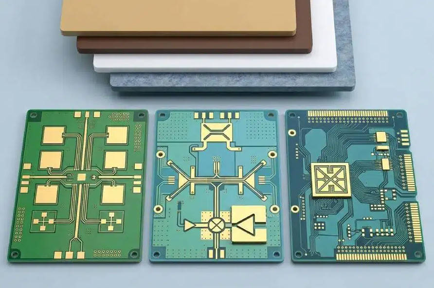
As electronic devices become smaller and more powerful, the demand for efficient thermal management has skyrocketed. Standard FR4 boards often struggle to dissipate the immense heat generated by modern high-power components, leading engineers to turn toward Metal Core Printed Circuit Boards (MCPCBs). Among these, aluminum is the most popular base material due to its optimal balance of thermal conductivity, durability, and cost-efficiency. Whether you are an electronics engineer designing the next generation of automotive headlights or a procurement manager sourcing boards for industrial power supplies, understanding the structural and functional nuances between single-sided and double-sided aluminum PCBs is critical for ensuring project success and hardware reliability.
What is a Single Layer Aluminum PCB?
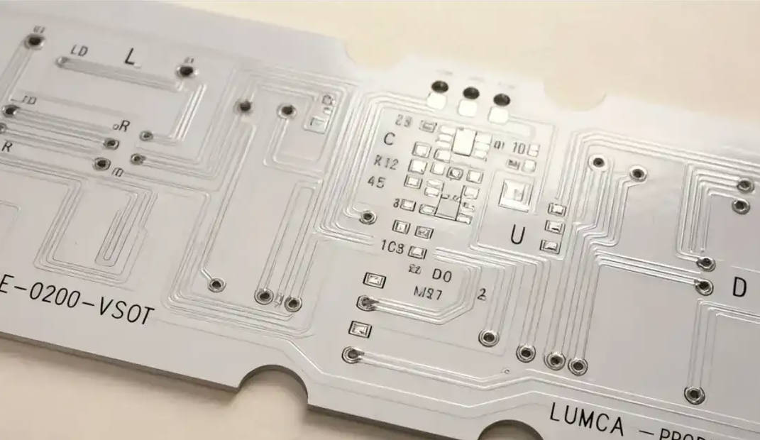
A single layer aluminum PCB is the most fundamental and widely utilized type of metal core board in the electronics industry. Because the design limits circuitry to just one side of the board, it requires minimal manufacturing steps compared to multi-layer counterparts. The foundational purpose of this board is to draw heat away from surface-mounted components and transfer it through the core to a broader heat sink or ambient air.
Structure and Composition
The architecture of a single layer aluminum PCB consists of three distinct functional layers seamlessly laminated together under high heat and pressure:
- Circuit Layer (Copper Foil): The topmost layer is composed of electrolytic copper foil, typically ranging from 1 oz to 3 oz in thickness depending on the current-carrying requirements. All surface-mount devices (SMDs) and circuit traces are etched onto this single plane.
- Dielectric Layer: Sitting directly beneath the copper is the most critical component of the MCPCB—the dielectric layer. This incredibly thin (usually 50μm to 200μm) layer of thermally conductive but electrically insulating polymer dictates the board’s overall thermal performance. High-quality dielectrics boast a thermal conductivity rating between 1.0 W/m·K and 3.0 W/m·K.
- Aluminum Base Layer: The foundational substrate is a solid sheet of aluminum alloy (commonly 5052, 6061, or 1060 series). Ranging from 1mm to 3mm in thickness, this metal backing acts as a robust structural support and a highly efficient heat spreader.
Key Advantages and Limitations
The standout advantage of single layer aluminum boards is their unbeatable cost-to-performance ratio. Because they do not require via drilling, hole plating, or complex lamination cycles, manufacturing yields are exceptionally high, and turnaround times are short. They offer phenomenal heat dissipation, drastically extending the lifespan of high-wattage components like LEDs and power transistors.
However, the primary limitation is routing flexibility. With only one copper layer available, engineers cannot overlap traces. If a circuit design is highly complex with numerous intersecting paths, it simply cannot be routed on a single layer without relying heavily on zero-ohm resistors or jumper wires, which can degrade signal integrity and increase assembly time.
What is a Double Layer Aluminum PCB?
When an electronic design demands dense component placement and intricate routing that a single surface cannot accommodate, engineers must step up to a double layer aluminum PCB. Unlike standard double-sided FR4 boards, integrating two layers of copper with a solid metal core introduces significant engineering hurdles, particularly concerning electrical isolation.
Complex Architecture and Vias
Double layer aluminum PCBs generally come in two primary configurations, each with distinct structural characteristics:
- Aluminum Base with Two Top Copper Layers: In this setup, the aluminum core remains at the bottom of the stack. Above the metal core is a dielectric layer, followed by a copper layer, another dielectric layer, and a final top copper layer. Vias connect the two copper layers but do not penetrate the aluminum base.
- Central Aluminum Core (True Double-Sided): Here, the aluminum serves as the central spine of the board. The stack-up features dielectric and copper layers on *both* the top and bottom of the metal core. To connect the top and bottom copper layers, manufacturers must drill vias completely through the aluminum. To prevent catastrophic short circuits, these holes are drilled oversized, filled with a highly insulating resin, and then re-drilled and plated with copper.
The latter configuration requires specialized manufacturing techniques, significantly increasing the baseline technology requirements of the PCB fabrication facility.
Pros and Cons of Double-Sided Designs
The greatest strength of the double-sided aluminum PCB is its high routing density paired with superior thermal management. It allows engineers to shrink the physical footprint of complex power systems, enabling miniaturization without sacrificing heat dissipation. Furthermore, placing components on both sides of the board maximizes spatial efficiency inside tight product enclosures.
On the downside, the cost is substantially higher. The necessity of resin-filled vias, multiple lamination cycles, and precision drilling into metal increases both the raw material costs and the fabrication time. Furthermore, the additional dielectric layers can slightly impede the direct thermal path from the top components to the aluminum core compared to a single layer design.
Head-to-Head Comparison: Single Layer vs Double Layer
To fully grasp what’s the difference between these two variations, a direct comparison of their critical engineering parameters is necessary. The choice between single and double-layer MCPCBs will fundamentally alter your project’s budget, thermal profile, and physical dimensions.
| Feature | Single Layer Aluminum PCB | Double Layer Aluminum PCB |
|---|---|---|
| Copper Layers | One (Top side only) | Two (Top/Bottom or Top/Top) |
| Component Mounting | Single-sided | Double-sided (in central core design) |
| Thermal Resistance | Extremely Low (Direct path to base) | Slightly Higher (Due to extra dielectric) |
| Manufacturing Cost | Low (Cost-effective for high volume) | High (Complex via insulation required) |
| Routing Density | Low (No overlapping traces) | High (Vias enable complex routing) |
| Lead Time | Short (Standard fabrication process) | Longer (Requires resin filling and multi-lamination) |
Thermal Management and Heat Dissipation
Both boards excel at thermal management, but they achieve it differently. The single layer board offers the path of least resistance: heat travels from the component, through the thin copper, across the single dielectric layer, and directly into the aluminum heat sink. In a double layer board, the heat from top-mounted components may have to travel through an inner copper layer and an additional dielectric barrier before reaching the aluminum core. While still vastly superior to FR4, engineers must account for this slight increase in thermal resistance during the thermal simulation phase of the design.
Manufacturing Complexity and Cost
Cost disparity is the most notable difference for procurement teams. A single layer aluminum board is generally only slightly more expensive than a standard single-sided FR4 board, largely due to the raw material cost of the metal. A double layer aluminum board, however, can cost up to three to five times more than its single-layer counterpart. The process of pre-drilling the aluminum, filling it with insulating epoxy, curing it, and then performing standard via plating introduces high defect risks and requires strict quality control, all of which drive up the final price per unit.
Typical Applications for Each Type
Because of their distinct performance profiles and price points, single and double layer aluminum PCBs dominate completely different sectors of the electronics market.
Where to Use Single-Sided Aluminum Boards:
This type of board is the undisputed king of the lighting industry. High-power LEDs generate immense localized heat that must be dissipated rapidly to prevent color shifting and premature diode failure. Because LED arrays typically require very simple routing (series or parallel strings), a single layer is perfectly adequate. Common applications include:
- Automotive headlights and taillights
- Street and architectural lighting
- Backlight units for flat-panel displays
- Basic audio amplifiers and motor drivers
When to Upgrade to Double-Sided Aluminum PCBs:
Double layer boards are reserved for applications where intense heat generation is paired with sophisticated logic or high-density power conversion. When the physical real estate is constrained, and a cooling fan is not an option, double-sided aluminum is the answer. Common applications include:
- High-voltage power supplies and converters (AC-DC, DC-DC)
- Electric Vehicle (EV) battery management systems (BMS)
- Solid-state relays and industrial power controllers
- Aerospace and military guidance electronics
How to Choose the Right Aluminum PCB for Your Project
Selecting the right metal core board requires balancing your thermal requirements against your budget and spatial constraints. Ask yourself the following questions during the schematic phase:
Is my circuit topology simple enough to be routed on a single plane? If you are designing an LED panel or a basic power regulator, spend time optimizing the layout to fit on a single layer. The cost savings in mass production will be substantial.
Do I have extreme space constraints? If your device enclosure requires a tiny form factor, you may be forced to use a double layer board simply to fit all the necessary components and routing into the required dimensions. If you choose this route, ensure you collaborate closely with your PCB manufacturer to specify the correct dielectric thermal conductivity and via insulation materials.
What is the operating environment? In environments with high ambient temperatures where active cooling (fans) cannot be used, prioritizing the lowest possible thermal resistance is key. Sometimes, using a slightly larger single-layer board is thermally superior to a dense, compact double-layer board.
Conclusion: Maximizing Performance with the Right MCPCB
Understanding the intricacies of Single Layer vs Double Layer Aluminum PCBs is the key to designing electronics that are both highly reliable and economically viable. Single-layer boards offer unmatched simplicity, rapid manufacturing times, and direct thermal pathways, making them the industry standard for LED lighting and basic power applications. Conversely, double-layer aluminum boards push the boundaries of what is possible in compact hardware design, providing complex routing and dual-sided component mounting at the expense of higher manufacturing complexity and cost.
By carefully analyzing your project’s routing density, thermal load, and budget, you can select the appropriate aluminum PCB architecture. Partnering with an experienced PCB fabricator who understands the nuances of metal core drilling and dielectric lamination will further ensure that your final product operates flawlessly, even under the most demanding thermal conditions.