What is the difference between an Aluminum PCB and a Copper Core PCB? The primary difference lies in their thermal conductivity, weight, and cost. Copper Core PCBs offer superior thermal conductivity (typically 384 W/m·K) and excellent heat dissipation for high-power, high-frequency applications, but they are heavy and expensive. In contrast, Aluminum PCBs provide moderate thermal conductivity (1 to 9 W/m·K) but are highly cost-effective, lightweight, and perfectly suited for general thermal management applications like LED lighting and consumer electronics. Choosing between them depends entirely on your project’s thermal load, budget, and weight constraints.
As modern electronic devices become smaller, faster, and significantly more powerful, managing the heat generated by these components has become a critical engineering challenge. Metal Core Printed Circuit Boards (MCPCBs) have emerged as the industry standard for thermal management. Among the various metal substrates available, aluminum and copper are the two most prominent contenders. While both serve the fundamental purpose of drawing heat away from critical components, their material properties dictate vastly different use cases. In this comprehensive guide, we will explore the structural nuances, performance metrics, and application suitability of Aluminum PCBs versus Copper Core PCBs to help you make an informed engineering decision.
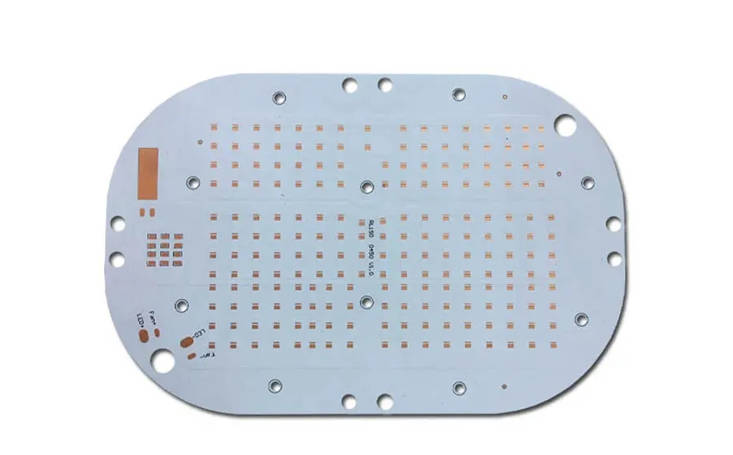
What is an Aluminum PCB?
An Aluminum PCB is a type of Metal Core Printed Circuit Board (MCPCB) that utilizes an aluminum alloy base material as the primary heat spreader. The structural composition typically consists of three distinct layers: a copper circuit layer for electrical routing, a specialized dielectric layer designed for thermal conductivity and electrical isolation, and the thick aluminum base layer. The aluminum base is usually composed of alloys such as 5052, 6061, or 1060, which are selected for their excellent balance of mechanical strength and thermal properties.
The magic of the Aluminum PCB lies heavily in its dielectric layer. This layer is engineered using thermally conductive ceramics mixed with a polymer base, allowing heat to pass from the heat-generating components (like surface-mounted LEDs or power transistors) directly down to the aluminum core. Because aluminum is a naturally excellent heat sink, it disperses this thermal energy into the surrounding air or into an attached external heat sink. This prevents localized hot spots that could severely degrade component lifespan or cause catastrophic failure.
Historically, Aluminum PCBs gained massive popularity alongside the explosion of the LED lighting industry. High-brightness LEDs generate a substantial amount of heat, and traditional FR4 fiberglass boards simply cannot dissipate it fast enough. Aluminum substrate boards provided the perfect solution: they are cheap to produce in massive volumes, light enough to be mounted in standard fixtures, and possess enough thermal conductivity to keep commercial LEDs running for tens of thousands of hours.
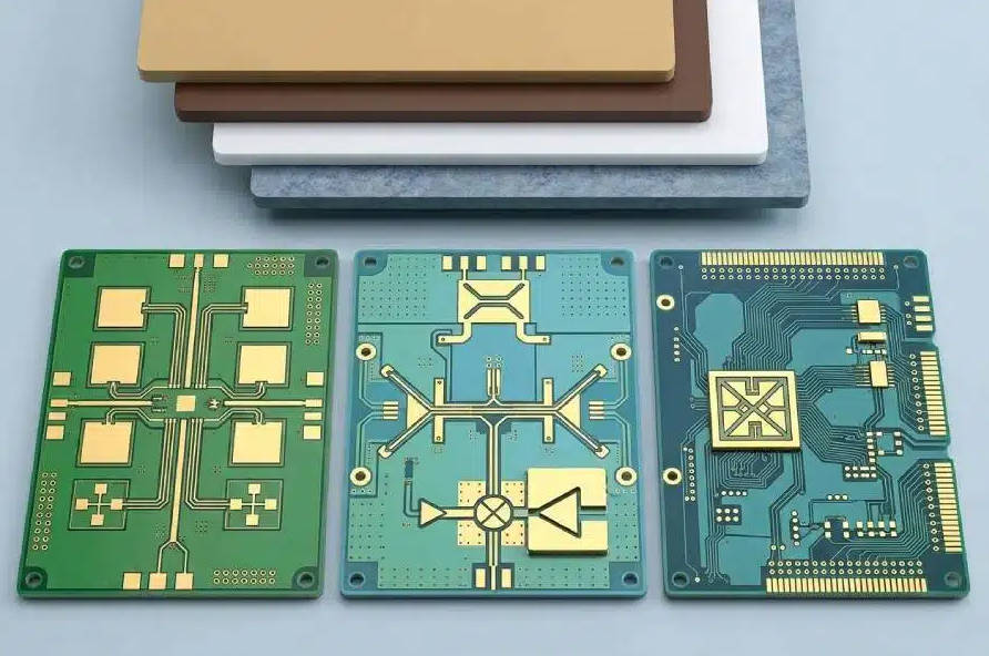
What is a Copper Core PCB?
A Copper Core PCB takes the concept of thermal management to its absolute maximum. Instead of aluminum, these boards feature a solid copper substrate as the foundational heat-spreading layer. Structurally, they are similar to their aluminum counterparts—featuring a circuit layer, a dielectric layer, and a metal base—but the use of heavy copper fundamentally changes the board’s performance characteristics. In some advanced configurations, such as Thermoelectric Separation Copper PCBs, the copper core directly touches the heat-generating component, entirely bypassing the dielectric layer to achieve a thermal resistance approaching zero.
Copper is widely recognized as one of the best thermally conductive metals available for commercial manufacturing. Its ability to absorb and transfer thermal energy is roughly double that of aluminum. When engineers design systems for extremely harsh environments—such as automotive EV power modules, high-frequency RF applications, or industrial laser systems—they often turn to copper base PCBs. These applications generate intense, rapid bursts of heat in highly localized areas. Copper’s rapid thermal transfer rate pulls this heat away instantaneously, protecting sensitive semiconductor junctions from melting or failing.
However, engineering is always a game of trade-offs. The impressive thermal performance of copper comes with strict penalties in weight and material cost. Manufacturing a Copper Core PCB is notoriously difficult because the metal is much harder on routing and drilling tools than aluminum. Consequently, Copper PCBs are generally reserved for premium, high-stakes applications where thermal failure is not an option and budget constraints are secondary to raw performance.
Key Differences: Aluminum vs. Copper Substrates
Thermal Conductivity and Heat Dissipation
When asking, “Which metal core PCB handles heat better?”, the answer decisively points to copper. The thermal conductivity of pure copper is approximately 384 W/m·K (Watts per meter-Kelvin), whereas standard aluminum alloys used in PCBs hover around 237 W/m·K. However, it is essential to note that the overall thermal performance of standard MCPCBs is heavily bottlenecked by the dielectric layer. In standard configurations, an Aluminum PCB will offer an effective thermal conductivity of 1 to 9 W/m·K, depending on the quality of the prepreg used. Copper PCBs utilizing standard dielectric layers will see similar limitations, though the base metal still spreads the heat more efficiently across the board’s surface.
Where copper truly creates a massive gap is in thermoelectric separation technology (also known as direct thermal path). In these advanced Copper Core PCBs, the heat pad of the component is soldered directly to the copper base, bypassing the insulating dielectric layer entirely. This results in an extraordinary thermal conductivity of up to 400 W/m·K right at the source of the heat. Aluminum cannot easily utilize this technology due to the difficulty of plating and soldering directly onto an exposed aluminum surface without specialized, expensive surface treatments.
Weight, Density, and Physical Constraints
Physical weight is a critical factor in aerospace, automotive, and portable electronics engineering. Aluminum has a density of roughly 2.7 g/cm³, making it an incredibly lightweight metal. This makes Aluminum PCBs highly desirable for applications like automotive headlights, aviation interior lighting, and consumer electronics where reducing overall vehicle or device weight directly translates to improved fuel efficiency or user comfort.
Conversely, copper is a dense, heavy metal with a density of about 8.96 g/cm³—making it more than three times heavier than aluminum. A fully assembled Copper Core PCB is noticeably heavy. If an engineer is designing a payload for a drone, a satellite, or a lightweight portable device, the mass of a copper substrate might immediately disqualify it from the design. Therefore, the choice between the two often hinges not just on thermal needs, but on strict weight budgets allocated to the PCB assembly.
Cost Efficiency and Manufacturability
From a procurement and manufacturing standpoint, Aluminum PCBs are the undisputed champions of cost-efficiency. Aluminum as a raw material is abundant and relatively inexpensive on the global market. Furthermore, aluminum is a softer metal compared to copper. During the PCB fabrication process, routing, drilling, and v-scoring aluminum substrates causes significantly less wear and tear on manufacturing drill bits and router profiles. This ease of machinability drastically lowers the manufacturing overhead, allowing for highly competitive pricing, especially in high-volume production runs.
Copper Core PCBs represent a premium investment. The raw material cost of copper fluctuates but is consistently much higher than aluminum. Additionally, copper’s toughness means that PCB manufacturers must run their CNC machines at slower speeds and replace their drill bits much more frequently to avoid bit breakage and poor hole-wall quality. These manufacturing challenges increase labor time, machine time, and consumable costs, which are ultimately passed down to the buyer. Prototyping and manufacturing copper boards require a substantial budget, making them viable only for high-margin or mission-critical projects.
Pros and Cons of Aluminum PCBs
Understanding the distinct advantages and limitations of aluminum circuit boards is vital for determining if they fit your project requirements. The primary advantage is their exceptional cost-to-performance ratio. Aluminum provides excellent thermal management for 90% of standard high-power applications at a fraction of the cost of copper. Furthermore, their lightweight nature makes them versatile. They are also environmentally friendly, as aluminum is highly recyclable and non-toxic.
On the downside, Aluminum PCBs are generally limited to single-sided or simple double-sided designs. Creating highly complex multilayer Aluminum PCBs is notoriously difficult due to the complexities of insulating vias through the aluminum core. Furthermore, aluminum is susceptible to oxidation if not properly treated, and its coefficient of thermal expansion (CTE) differs significantly from standard copper traces. Under extreme and rapid temperature fluctuations, this CTE mismatch can occasionally lead to micro-fractures in the solder joints or the dielectric layer.
Pros and Cons of Copper Core PCBs
The pros of Copper Core PCBs revolve entirely around elite thermal and electrical performance. With a much higher thermal conductivity, they are capable of cooling high-frequency, high-current, and high-density component clusters that would otherwise melt standard substrates. Copper also boasts excellent dimensional stability. Its CTE is much closer to that of the copper traces and ceramic components mounted on the board, meaning that during extreme thermal cycling, the board expands and contracts uniformly, vastly reducing the risk of component detachment or trace shearing.
However, the cons are significant and impossible to ignore. The most prominent is the high cost of raw materials and complex fabrication, making them economically unviable for budget-conscious consumer goods. Secondly, the extreme weight of the copper base heavily limits its use in weight-sensitive applications. Lastly, manufacturers must employ specialized chemical processes to prevent the heavy copper base from tarnishing or corroding over time, adding another layer of complexity to the supply chain.
Side-by-Side Comparison Matrix
To provide a clear, high-level overview, the following table summarizes the primary differences between Aluminum and Copper Core PCBs across several critical engineering metrics.
| Feature / Metric | Aluminum PCB | Copper Core PCB |
|---|---|---|
| Base Thermal Conductivity | ~237 W/m·K | ~384 W/m·K |
| Dielectric Thermal Conductivity | 1.0 – 9.0 W/m·K | 1.0 – 9.0 W/m·K (Up to 400 with Thermoelectric Separation) |
| Material Density (Weight) | 2.7 g/cm³ (Lightweight) | 8.96 g/cm³ (Heavy) |
| Manufacturing Cost | Low to Moderate (Highly economical) | High (Premium pricing) |
| Machinability | Easy to drill, route, and punch | Difficult; causes rapid tool wear |
| Primary Applications | LED lighting, power supplies, motor controllers, consumer electronics | Automotive EVs, RF/Microwave circuits, heavy industrial power modules |
How to Choose the Right Metal Core PCB
Choosing between an Aluminum PCB and a Copper Core PCB requires a holistic view of your product’s lifecycle, operating environment, and commercial goals. Ask yourself: What is the maximum operating temperature of the components, and how fast must the heat be evacuated? If you are designing an array of high-power SMD LEDs for a street lamp, the heat is constant but manageable. An Aluminum PCB will easily dissipate this heat while keeping the heavy light fixture within safe weight limits and maintaining a high profit margin.
Conversely, if you are designing a compact power inverter for an electric vehicle, the system will face immense current spikes, extreme localized heat generation, and severe ambient thermal cycling. In this scenario, the cost of a thermal failure is catastrophic. The high density and superior thermal transfer of a Copper Core PCB—especially one utilizing thermoelectric separation—become absolute necessities. The higher cost is easily justified by the reliability and safety it guarantees.
Conclusion
In the ongoing debate of Aluminum PCB vs Copper Core PCB, there is no universal “winner.” Instead, there is only the right tool for the specific job. Aluminum PCBs remain the backbone of the thermal management industry, democratizing high-power electronics and LED lighting by providing a perfect blend of low cost, light weight, and reliable heat dissipation. They are the workhorses of the modern electronic landscape.
Copper Core PCBs, on the other hand, are the specialized elite. They step in when physics pushes systems to their limits, offering unparalleled thermal conductivity and structural stability under extreme stress. By carefully evaluating your thermal loads, budget restrictions, and mechanical constraints, you can select the ideal metal substrate that ensures your electronic design runs efficiently, safely, and reliably for years to come.