Choosing between M6, M7 and M8 laminate comes down to one number: dissipation factor (Df). Each step down in Df buys you more usable channel length at a given data rate, and costs more per panel. M6 handles most 28–56 Gbps work comfortably. M7 becomes the default once you reach 112 Gbps PAM4 over meaningful distances. M8 is reserved for the longest channels and the tightest loss budgets, where the extra material cost is cheaper than adding retimers or shortening the route. This article explains what the grades actually measure, how much difference each one makes in a real channel, and where the crossover points sit.
What M6, M7 and M8 Actually Refer To
M6, M7 and M8 are not IPC-defined classes. They are supplier grade names — most commonly associated with Panasonic’s Megtron series — that the industry has adopted as shorthand for tiers of low-loss copper clad laminate (CCL). Other laminate suppliers use different naming, so a grade label alone does not tell you the electrical performance; the datasheet does.
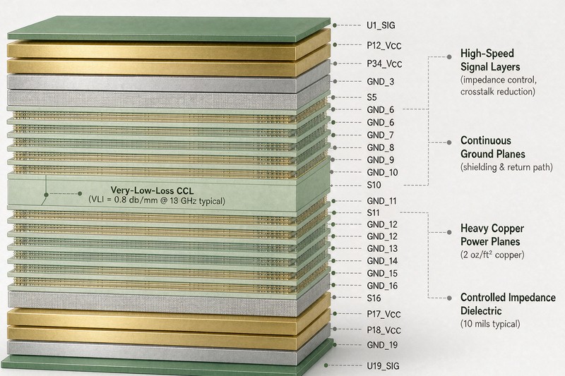
CCL is the base material of a rigid PCB: a dielectric system (resin plus reinforcement, typically glass cloth) bonded to copper foil on one or both sides. During lamination, multiple CCL cores and prepreg layers are pressed together to build the final stackup. The electrical behaviour of the finished board depends heavily on which CCL grade sits under each signal layer.
Two properties matter most for high-speed design:
- Dk (dielectric constant) — determines how fast a signal propagates and how tightly the field couples to the dielectric. Lower Dk generally means faster propagation and slightly thinner dielectric for a target impedance.
- Df (dissipation factor, or loss tangent) — determines how much signal energy the dielectric converts to heat. This is the property that separates M6 from M7 from M8.
Copper roughness is the third variable, and it is easy to overlook. At the frequencies where M7 and M8 become relevant, the conductor loss contributed by the copper-to-dielectric interface can rival the dielectric loss. A low-Df laminate paired with rough copper will not deliver the loss performance the datasheet implies, so the foil profile has to be specified alongside the grade.
How the Grades Compare
The table below describes the general positioning of each grade. Exact values differ by supplier, resin system and test frequency, so treat these as typical ranges rather than specification limits and confirm against the laminate datasheet you are actually buying.
| Grade tier | Typical Df range (at ~10 GHz) | Relative material cost | Where it is normally used |
|---|---|---|---|
| Standard FR-4 | ~0.015–0.020 | Baseline | Low-speed digital, power, consumer mainboards |
| Mid-loss (M4 class) | ~0.010–0.014 | ~1.5–2x | 10–28 Gbps short channels |
| M6 | ~0.008–0.010 | ~2–3x | 28–56 Gbps, AI server boards and accelerator cards |
| M7 | ~0.005–0.007 | ~3–4x | 112 Gbps PAM4 long channels, 800G optics, high-end switching |
| M8 | ~0.003–0.005 | ~4–6x | Tightest loss budgets, 224 Gbps development, long backplanes |
On a high-speed PCB design, the grade also interacts with the rest of the channel: the laminate sets the loss floor, but via structure and copper roughness determine how close to that floor the finished board actually gets.
The cost multipliers are indicative and move with resin supply and copper pricing. During periods of tight supply of high-end laminate, the spread between grades tends to widen rather than narrow.
One practical point: moving from M6 to M7 does not change Dk dramatically. The gain is almost entirely in Df, which means the benefit shows up as reduced insertion loss at high frequency rather than as a change in impedance or propagation delay. If your stackup is already impedance-correct, a grade change generally does not force a full re-layout, but it does require re-verifying the loss budget.
Where Loss Actually Bites in a Channel
Dielectric loss scales with frequency and with trace length. A material that is perfectly adequate for a 15 cm route on an accelerator card can fail the same signalling standard when the route stretches to 60 cm across a midplane. This is why the grade decision cannot be separated from the interconnect length.
Insertion loss is commonly expressed in dB per inch at a given frequency. Total channel loss is what the SerDes has to overcome, and modern SerDes equalisation (CTLE, DFE) can recover a surprising amount — but it has limits, and pushing equalisation to its limit usually shows up as reduced margin rather than as a clean failure.
Three factors interact when you assess whether a grade is sufficient:
- Data rate and modulation — PAM4 at 112 Gbps has a much smaller eye opening at the receiver than NRZ at 28 Gbps, so it tolerates less loss before the margin collapses.
- Route length — loss accumulates linearly with distance. Doubling the length roughly doubles the loss in dB.
- Number of discontinuities — vias, connectors and breakout regions add loss and reflection. A channel that looks fine on paper for trace loss can still fail because of via stubs.
This is also where the rest of the design has to cooperate. controlled impedance keeps reflections from compounding the loss, and via design — back-drilling where stubs are unavoidable — often delivers more improvement per dollar than moving up one laminate grade. On a dense multilayer PCB, the layer assignment matters as much as the material: a high-speed signal routed on a layer adjacent to a rough power plane will not behave the way the laminate datasheet predicts.
Matching a Grade to the Application
Rather than defaulting to the highest grade, it is usually better to work backwards from the interface and the route length. The following is a starting framework; the actual decision should be confirmed with channel simulation using the specific laminate and copper foil you plan to specify.
| Application | Typical interface | Common starting grade | Notes |
|---|---|---|---|
| General industrial and consumer boards | Up to 10 Gbps | Mid-loss FR-4 | M6 usually unnecessary |
| AI accelerator cards / short board routes | 28–56 Gbps | M6 | Short routes, M6 has sufficient margin |
| 800G switching and optical modules | 112 Gbps PAM4 | M7 | Long channels need M7; very short routes can be evaluated on M6 |
| Long backplanes / midplanes | 112 Gbps and above | M7 or M8 | Fix via stubs before upgrading material |
| 224 Gbps development | 224 Gbps PAM4 | M8 | Also requires ultra-smooth copper foil |
Note the recurring theme: before paying for a better laminate, confirm that the via structure is clean. Back-drilled vias on M6 frequently outperform non-back-drilled vias on M8, because stub resonance is a reflection problem rather than a dielectric problem.
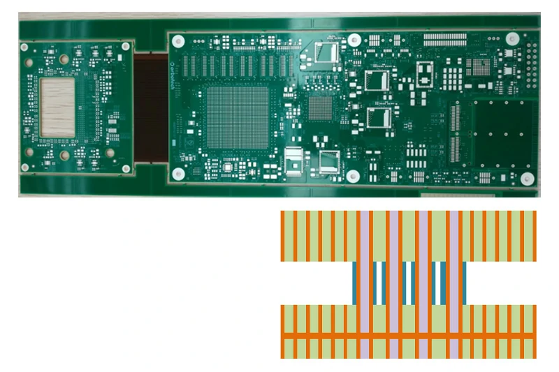
It is also worth comparing against the alternative of a hybrid stackup. Using a premium low-loss grade only on the signal layers that carry the fast interfaces, and a conventional FR4 PCB material on power, ground and low-speed layers, keeps most of the performance while controlling cost. Hybrid constructions are common in production for exactly this reason, though they introduce their own press and reliability considerations that have to be validated.
What to Confirm Before Specifying a Grade
From a procurement standpoint, laminate grade is not just an electrical decision. High-end grades have fewer qualified suppliers, longer lead times and more price volatility than standard materials. Confirming availability early often matters more than optimising the last fraction of a dB.
Points worth settling before the design is released:
- Exact laminate and prepreg part numbers, not just the grade name — different resin systems within the same tier behave differently at reflow.
- Copper foil profile — specify the foil type together with the grade, since it materially affects conductor loss.
- Glass cloth style — spread glass or flat-open weave reduces skew caused by fibre weave effect on long differential pairs.
- Availability and lead time for the specific construction, including the copper weights you need.
- Press capability — not every fabricator can laminate every high-grade system reliably, particularly in hybrid builds.
- CAF and thermal reliability — some very low-loss resins behave differently under moisture and thermal cycling, which matters for PCB Raw Materials Library selection in harsh environments.

Early conversation with the fabricator pays off here. Because high-grade laminate often has to be ordered in before the panel run, a grade change late in the design cycle can add weeks to the schedule — more than the cost difference between grades. Reviewing the material choice during DFM is the cheapest point at which to make that decision.
Conclusion
The M6 / M7 / M8 decision is fundamentally a loss-budget decision, not a quality decision. M6 covers most 28–56 Gbps work and short AI accelerator routes. M7 is the practical default for 112 Gbps PAM4 where routes are more than a few inches long, because PAM4 has far less margin to give. M8 earns its premium only on the longest channels or the most aggressive forward-looking designs, and only after the via structure has already been optimised.
Two things are worth remembering from the analysis above. First, the grade label is shorthand — always specify the actual laminate part number, the copper foil profile and the glass style, because those determine the realised performance. Second, a via stub or a rough copper surface can erase the benefit of moving up a grade, so geometry and foil should be resolved before material cost is escalated.
If you are working on a design where the loss budget is uncertain, send the interface rate, route length and stackup constraint, and we can review whether the specified grade matches what the channel actually needs.
FAQ
Are M6, M7 and M8 defined by an IPC standard?
No. These are supplier grade names that the industry uses as shorthand for tiers of low-loss laminate. There is no IPC document that defines what M7 must measure, so the datasheet for the specific laminate you are buying is the authoritative reference.
Does moving from M6 to M7 require a new stackup or re-layout?
Usually not a full re-layout. The gain from M6 to M7 is mainly in Df rather than Dk, so if the stackup is already impedance-correct the geometry generally still works. The loss budget should be re-verified, and the new material’s Dk should be confirmed before the impedance calculation is reused.
Is M8 always better than M7?
Only for loss. M8 has lower Df, which helps on long channels, but it costs more, may have longer lead time, and does nothing for reflections caused by via stubs or impedance discontinuities. On a short, well-designed channel the extra cost often buys no usable margin.
Can a hybrid stackup reduce the cost of a high-grade design?
Yes. Using a premium low-loss laminate only on the layers that carry high-speed signals, and a conventional material elsewhere, is a common production approach. It needs to be validated with the fabricator, since hybrid builds have their own press and reliability considerations.